 |
|||
|
|
|||
| ||||||||||
|
|  MIL-S-19557/10A(AS)
1.0 PURPOSE
The purpose of the test set, during-testing of the Air Turbine Starter (ATS), is to
assure adequacy of the speed signal for operation of the frequency sensing relay (FSR).
2.0 ELECTRICAL REQUIREMENTS
Power Input: 24 to 28 VDC
Signal input: Speed signal from ATS
Signal output: 7.3 volt pulses at speed signal frequency
2.1 The test set simulates the input circuit of the FSR and utilizes FSR components. Input
capacitors simulate connector filter pin capacitances of the FSR and MSDC.
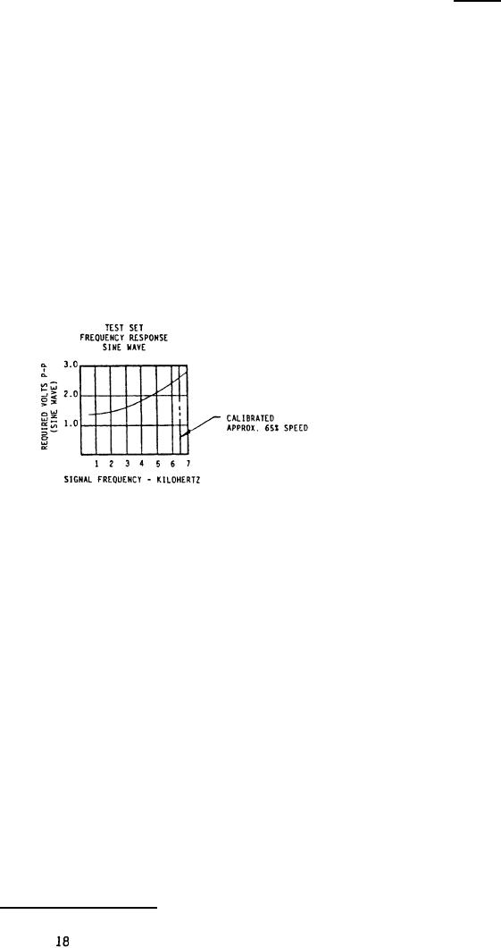
2.2 Signal threshold is adjusted to a higher level than in the FSR. Therefore, adequacy of
the ATS speed signal is assured, if all 24 pulses per revolution appear at the test set
output. The curve below shows test set frequency (speed) threshold requirements.
3.0 ATS TESTING REQUIREMENTS
3.1 Test speeds are specified in the test procedure for the ATS. One speed shall be at 65%
(FSR cutoff).
3.2 The speed signal is acceptable when all 24 pulses per revolution are present at the
test set output. Presence of all 24 pulses shall be determined with an oscilloscope or
other equivalent means.
4.0 TEST SET CALIBRATION PROCEDURE
The following procedure shall be used for periodic calibration of the test set.
4.1 Connect a 26.0 0.5 VDC power supply to the 28 VDC input.
4.2 Connect an oscilloscope to the output and a sine wave oscillator to the input with
suitable instrument to measure input voltage.
4.3 Adjust the oscillator frequency to 6500 + 5 HZ and amplitude to 3.0 to 3.5 VPP (1.06 to
1.24 YRMS). Adjust the oscilloscope to indicate the output pulses.
4.4 Slowly decrease the oscillator amplitude until the output pulses disappear. Then
slowly increase the amplitude and determine the minimum input amplitude (at 6500 HZ)
which will produce all pulses at the output. The minimum amplitude shall be 2.56 to
If not within requirement remove the cover
2.62 volts P-P (0.905 to 0.926 volts RMS).
and adjust R12 to bring within tolerance.
4.5 Using the method of 4:4 determine the minimum input amplitude at 1000 HZ. It shall be
1.24 to 1.52 volts P-P (0.438 to 0.537 volts RMS). DO not adjust.
FIGURE 6. Test set specification.
|
|
Privacy Statement - Press Release - Copyright Information. - Contact Us |
