 |
|||
|
|
|||
| ||||||||||
|
|  MIL-S-23809C(OS)
Course test. Disconnect the dc leads to P34, given in 4.6.14
4.6.16
and 4.6.15,
and apply a 10 volt 400 Hz ac signal across pins L and M of P34.
Channel 8 of the oscillograph shall show a 400 Hz envelope 0.50 0.25 in.
wide If deflection is incorrect, adjust potentiometer R74 until
deflection is correct.
4.6.17
Steering relay test.
a.
to pins C
Transfer the ac input leads connected in 4.6.16
and D of P34. Channel 3 of the oscillograph shall show a 400 Hz envelope
0.19 0.06 in. wide.
b.
Remove the ac input lead from pin D of P34 and connect it to
pin E of P34. The ac envelope given in 4.6.17.a shall disappear, and
channel 3 of the oscillograph shall deflect 0.25 0.12 in. toward
channel 14.
Jumper between pins D and E of P34. The deflection given in
shall remain, and in addition the ac envelope given in 4.6.17.a
shall reappear.
4.6.18
Input level test. Set timer for a 30 second period. With loaded
film magazine installed, apply power (24 Vdc
to timer and oscillograph,
and 115 volts ac 400 Hz to recording panel) and run for a 30-second period.
Disconnect power, and remove and develop film. Random spikes which can be
attributed to shop equipment noise should be ignored. The exercise section
shall meet the requirements of 3.3.19.
Wire command. Connect the negative side of the 24 Vdc
4.6.19
source to pin e of P34. Channel 1 of the oscillograph shall deflect
0.50 0.25 in. toward channel 14.
Noisemaker test. With no time on the exercise timer, apply 24 Vdc
4.6.20
to pins T (positive) and P (negative) of P23. The current shall be within the
range of 0.3 to 0.6 ampere, and the noisemaker shall produce maximum noise out-
put to meet the requirements of 3.3.21.
NOTE: Noise output may be adjusted
in accordance with Dwg 3029766.
4.6.21
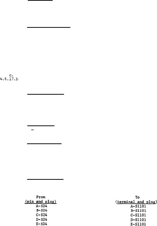
Cable continuity. Disconnect all electrical and hydraulic leads,
and make cable continuity checks as given in Table I below:
Table I
13
|
|
Privacy Statement - Press Release - Copyright Information. - Contact Us |
