 |
|||
|
Page Title:
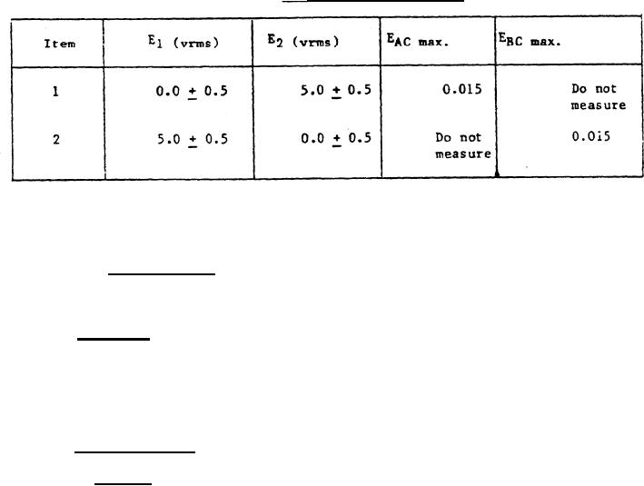
Table I. Maximum null voltages. |
|
||
| ||||||||||
|
|  MIL-S-48461B(AR)
3 . 3 . 3 Rotor voltages at null. The maximum rms value for all voltage
c o m p o n e n t s shall be as specified for each item of table I after the assembly
h a s been rotated about the roll axis to the position which reduces the
i n - p h a s e component of the measured output voltage to a minimum value. (See
4.6.2.3)
TABLE I. Maximum null voltages.
3.3.4 Spurius signal components. There shall be no periodic signal
E
E
components of EAC, EB C , E H , and JM with the exception of the 400 Hz
s i g n a l voltage and harmonics of the 400 Hz signal voltage. (See 4 . 6 . 2 . 4 )
3 . 3 . 5 S e t t l i n g t i m e . T h e assembly output voltages shall attain steady
s t a t e within one second of a 15 degree displacement of the roll axis. The
d i s p l a c e m e n t rate shall be not less than 150 degrees per second. (See 4.6.2.5)
3 . 4 S e a l i n g . W i t h an internal nitrogen pressure of 5.0 + 0.1 pounds per
s q u a r e inch gauge (psig), the assembly shall exhibit a pressure drop not
g r e a t e r than 0.2 psig for not less than 2 hours. The pressurized assembly
s h a l l be purged with dry nitrogen in accordance with BB-N-411, type I, grade
B , class 1 with a dewpoint of -25F or lower and shall have a final pressure
o f 0.0 + 0.2, -0.0 psig. ( S e e 4 . 6 . 4 )
3.5 E n v i r o n m e n t a l .
3 . 5 . 1 S h o c k . The assembly shall be capable of operating as specified
h e r e i n after exposure under the conditions of 3.1.3 to three half sine wave
s h o c k pulses of 40 + 4 gravity unit (g) for a duration of 18 + 3 milliseconds
( m s e c ) applied in each direction along three mutually perpendicular axes. In
a d d i t i o n , the assembly shall be capable of withstanding three half sine wave
s h o c k pulses of 100.0 + 10.0 g for a duration fo 1.5 + 0.2 msec applied in
each direction along three mutually perpendicular axes. (See 4.6.3.1)
7
|
|
Privacy Statement - Press Release - Copyright Information. - Contact Us |
