 |
|||
|
Page Title:
Non-Arming of safe and arming subassembly |
|
||
| ||||||||||
|
|  MIL-S-63383(AR)
Also included are all associated springs, locks and closures for
the above assembly.
Optional parts are:
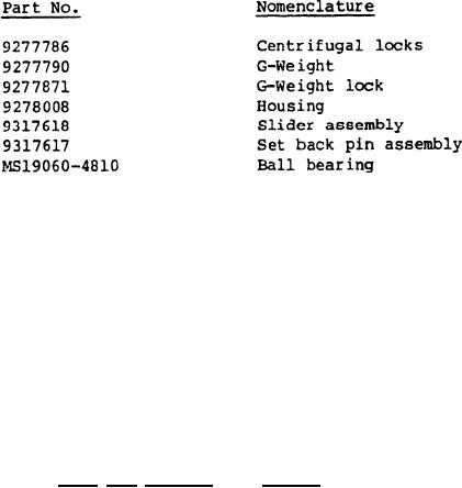
Closure firing pin, Part No. 9317591
Rear locks, Part No. 9278057
Slider, lock, Part No. 9278060
Rear lock springs, Part No. 9278109
And all associated closures.
Also included for the optional parts are all associated springs,
locks and closures for the above assembly.
The test sample must not contain the staked disc closure, Part
No. 9277812 for this test.
The slider shall be maintained in the correctly oriented
position during the arming and non-arming tests. The Contractor,
when necessary, may utilize an interim slider lock for test purposes.
The S&A assembly shall be tested as follows using approved spin
and testing equipment.
The S&A, after secured nesting in the spin fixture, shall be
spun up to the arming speed specified on the applicable drawing.
To verify that the set back pin is in the non-armed position,
the contractor shall attempt to arm the "G" weight (Dwg 9277790), by
applying the minimum arming force as stated on the applicable
drawing. The S&A subassembly shall not arm. The force on the "G"
weight shall then be released,
The set back pin assembly, (Dwg 9317617), shall be moved to the
armed position and held in place. Arming force shall be as
specified in drawing 9317620.
17
|
|
Privacy Statement - Press Release - Copyright Information. - Contact Us |
