 |
|||
|
Page Title:
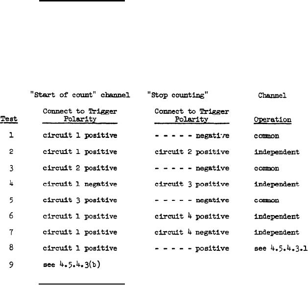
Table IV. Electronic Counter Settings |
|
||
| ||||||||||
|
|  MIL-T-22913C(OS)
4.5.4.1.2. Measure and record the maximum and minimum time intervals for
at least four cycles, as read by the electronic counter, for each test
specified In Table IV. In addition to meeting the time limit specified
for test 8, the reading shall be repeatable within 2 ms.
(b) For test 9 (circuit 5). Connect terminal 17 of P-152 to the
"start of count" and stop of count" leads of the electronic counter.
Connect the ground terminal of the timer interval section of the elec-
tronic counter to the zero volt terminal of the dc power supply. Trig-
gering level on the electronic counter shall be positive three volts
plus or minus one volt dc less than the voltage measured in 4.5.4.1.2.
Measure and record the maximum and minimum time intervals for at least
four cycles, as read by the electronic counter. All other timing cir-
cuits are disconnected from the counter during test 9.
TABLE IV.
ELECTRONIC COUNTER SETTINGS
(c) For tests 11 and 13. Connect the negative terminal of the 6
volt power supply to 19-P152 and the positive terminal to 18-P152. Join
the ground terminal of the oscilloscope to the center tap of the power
supply and connect to 20-P152. Connect 21-P152 to the input terminal of
the oscilloscope. Set the sweep at 20 ms per centimeter; adjust sweep,
if necessary, to obtain best reading. For test 11, set the oscilloscope
to trigger internally on a negative slope, dc signal; for test 13, trigger
19
|
|
Privacy Statement - Press Release - Copyright Information. - Contact Us |
