 |
|||
|
|
|||
| ||||||||||
|
|  MIL-T-23588C(OS)
4.4.3 Fungus. The transducer shall be tested for resistance to fungus in
accordance with method 508, procedure I of MIL-STD-81O and, thereafter, shall
meet the requirements of 3.5.3.
4.4.4 Pressure-Voltage sensitivity. Mount the transducer in a shock tube
and energize input terminals with a stable power supply. Output shall be
monitored on an oscilloscope with a suitable camera attachment. A step pres-
sure input (shock) shall be applied to the transducer and the output voltage
rise shall be photographed. The output shall meet the requirements of 3.5.4.
4.4.5
Zero output stability. Connect two 3000 ohm wire-wound resistors in
series across output terminals 1 and 2 with the midpoint grounded. Connect a
25,000 ohm potentiometer across output terminals 1 and 2, with a 200,000 ohm
resistor connected between the slider and input terminal 3. Apply 8 volts,
400 Hz or 8 volts dc to the input of the transducer and adjust the slider for
minimum output. With O psig applied to the transducer, vary the source voltage
over the range of 7.76 to 8.24 volts. The transducer shall meet the require-
ment of 3.5.5.
4.4,6 Using the test circuit of Figure 1, simulate the pressure cell with
four 120 ohm, nonreactive film resistors and measure the quadrature of the test
circuit as indicated on the oscilloscope (simulates transducer at O psig).
Shunt one arm of the simulating network with a 60,000 ohm, nonreactive film
resistor and measure the quadrature of the test circuit (simulates transducer
at 500 psig). Record these two readings, Remove the simulating resistors and
connect the pressure transducer. With O psig applied, measure the quadrature
of the circuit. Apply 500 psig to the transducer and measure the quadrature
voltage. Record these two readings. Determine the quadrature of the trans-
ducer at O psig by subtracting the value obtained at O psig with the simula-
ting network from that obtained with the transducer. The transducer shall
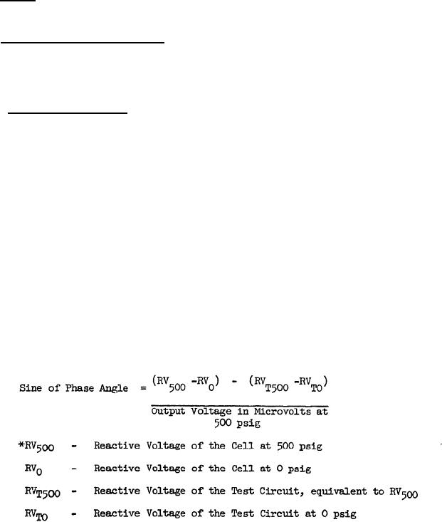
meet the requirement of 3.5.6.1. Record this value. The phase angle of the
output voltage with pressure applied may then be determined by the following
formula:
*All voltagegs expressed in microvolts.
The transducer shall meet the requirement of 3.5.6.2.
10
|
|
Privacy Statement - Press Release - Copyright Information. - Contact Us |
