 |
|||
|
Page Title:
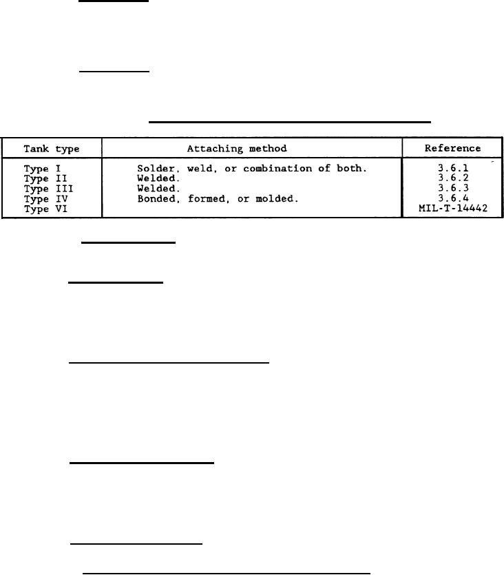
Table III. Means of attaching filler necks to fuel tanks |
|
||
| ||||||||||
|
|  MIL-T-46786B
3.5.2.1 Filler caps. The filler cap shall be constructed of either
material treated to resist corrosion or material inherently corrosion
resistant. The cap shall be captive chained or cabled to the strainer, when
provided, or to the tank, to prevent loss of the cap. The chain or cable shall
include a swivel joint and shall permit unobstructive refueling of the tank.
The captive cap components shall inherently resist corrosion and deterioration.
3.5.2.2 Filler neck. Filler necks shall be constructed of materials
treated to resist corrosion, compatible with the fuel tank, and shall be
affixed to the fuel tank in a manner compatible with the type of fuel tank
construction (see table III).
TABLE III.
Means of attaching filler necks to fuel tanks.
3.5.2.3 Filler strainer. Filler strainers shall be removable, constructed
of noncorrosive materials, 60-mesh screen, and shall be protected to prevent
damage caused by contact with the refueling nozzle.
3.5.3 Fuel tank drain. Fuel tanks shall be provided with a drain
connection separated from the fuel supply line and shall be of sufficient size
and located to permit complete drainage of condensation, contaminants, and
fuel. Unless otherwise specified herein, the drain connection shall be a
leakproof, threaded plug. When specified (see 6.2), a leakproof drain valve,
stopcock, or ball check release valve shall be acceptable. Drains or other
bottom fittings shall be protected against damage from impact.
3.5.4 Auxiliary fuel supply connection. When specified (see 6.2), an
auxiliary, 3-way, sealed, plug-type, selector valve, labeled "FUEL SUPPLY",
shall be provided with Provisions to accept a 5/16-inch, standard, flared
fitting conforming to SAE J512. A protective cap secured against-loss shall be
provided with the fitting. A corrosion-resistant circular faceplate shall be
mounted on the fuel selector valve and shall be marked with a double-ended
arrow indicating direction of rotation and labeled "OFF", "UNIT TANK", and
"AUXILIARY". A balance line shall be included when multiple tanks are
furnished.
3.5.5 Fuel line shutoff valve. When specified (see 6.2), a fuel line
shutoff valve shall be provided and shall be attached directly to the fuel tank
permitting removal of the tank prior to draining. The shutoff valve shall be
constructed of noncorrosive materials compatible with the fuel tank and the
fuel supply line. The valve shall be labeled "FUEL SHUTOFF". The valve shall
be provided with double-ended arrows showing direction of operations and
labeled at each end to indicate functional result (e.g., open and off).
3.5.6 Fuel measuring device. When specified (see 6.2), the fuel tank shall
be equipped with a fuel measuring device as specified herein.
3.5.6.1 Fuel liquid quantitv transmitter and indicator. When specified (see
6.2), a liquid quantity fuel transmitter shall be furnished and installed. The
|
|
Privacy Statement - Press Release - Copyright Information. - Contact Us |
