 |
|||
|
Page Title:
Simulator, Missile Firing SM-465/ASM-149A |
|
||
| ||||||||||
|
|  MIL-T-81404B(AS)
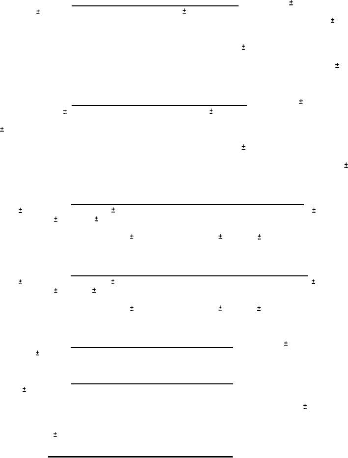
3.5.1.1.12 TEST switch position 9 (firing ready). With 115
11.5 volts
AC, 400
20 Hz applied at J101-B and 28
2 volts DC applied to J101-Z, the
headtone output shall not be present at J101-U. An input voltage of 22.5
().5 volts DC applied to J101-H shall cause the QUALITY meter to indicate on
the center of the line which determines the left edge of the circle zone.
When the input voltage at J101-H is increased to 31.0
1.2 volts DC, the
QUALITY meter shall indicate on the center of the line which determines the
right edge of the circle zone. The input resistance at J101-H shall be 25
2.5 ohms. When the voltage is removed from J101-Z, the headtone output shall
be present at J101-U.
3.5.1.1.13 TEST switch position 10 (firing signal). With 115
11.5
volts AC, 400
20 Hz applied to J101-B and 28
2 volts DC applied to J101-Z,
the headtone output shall not be present at J101-U. An input voltage of 22.5
0.5 volts DC applied to J101-Z shall cause the QUALITY meter to indicate on
the center of the line which determines the left edge of the circle zone.
When the input voltage at J101-Z is increased to 31.0
1.2 volts DC, the
QUALITY meter shall indicate on the center of the line which determines the
right edge of the circle zone. The input resistance at J101-Z shall be 23.8
2.5 ohms. When voltage is removed from J101-Z, the headtone shall be present
at J101-U.
With
3.5.1.1.14 TEST switch position 11 firing ready stray voltage).
115
11.5 volts AC, 400
20 Hz applied to J101-B, an input of 0.065
0.005
0.005 volts DC applied to J101-H shall cause the
volts AC or
0.065,
QUALITY meter to indicate in the rectangle zone. When the input voltage at
J101-H is increased to 0.100
0.005 volts AC or
0.100,
0.005 volts DC,
the QUALITY meter shall indicate in the BAD zone between the rectangle and
circle zones.
3.5.1.1.15 TEST switch position 12 (firing signal stray voltage). With
115
11.5 volts AC, 400
20 Hz applied to J101-B, an input of 0.065
0.005
volts AC or
0.065,
0.005 volts DC applied to J101-Z shall cause the
QUALITY meter to indicate in the rectangle zone. When the input voltage at
J101-Z is increased to 0.100
0.005 volts AC or
0.100,
0.005 volts DC,
the QUALITY meter shall indicate in the BAD zone between the rectangle and
circle zones.
3.5.1.1.16 TEST switch position 13 (meter test). With 115
11.5 volts
AC, 400
20 Hz applied to J101-B, the QUALITY meter shall indicate in the
circle zone.
3.5.1.1.17 TEST switch position 14 (master arm). An input voltage of
22.5
0.5 volts DC applied to J101-G shall cause the QUALITY meter to
indicate on the center of the line which determines the left edge of the
circle zone. When the input voltage at J101-G is increased to 31.0
1.2
volts DC, the QUALITY meter shall indicate on the center of the line which
determines the right edge of the circle zone. The input resistance at J101-G
shall be 25
2.5 ohms.
3.5.2 Simulator, Missile Firing SM-465/ASM-149A. The simulator shall be
manufactured in accordance with the applicable drawings of DL 1017AS100. The
simulator shall be capable of providing a means of checking the aircraft
intervalometer.
10
|
|
Privacy Statement - Press Release - Copyright Information. - Contact Us |