 |
|||
|
Page Title:
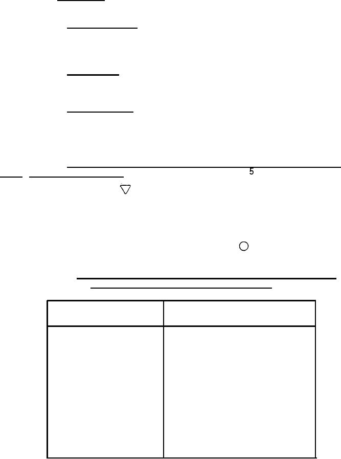
Table II. Frequencies and respective current components of signals originating in the Data Link Controller |
|
||
| ||||||||||
|
|  MIL-T-85378(AS)
normally mates with the data link pod. The test set shall provide a GO, NO-GO
indication confirming that the-data link signals supplied to the data link pod
are within the frequency ranges specified herein.
The test set shall meet the following electrical
3.6.1.2 Electrical.
requirements:
3.6.1.2.1 Multiplex input. The test set shall provide a virtual ground
input for the current source signal drive originating in the Data Link
Controller. The test set shall decode the signals when the current components
are of the magnitudes specified in table II.
3.6.1.2.2 Input power. The test set shall meet performance requirements
of this specification when 115 VAC, 400 Hz and +28 VDC input power from the
aircraft is in accordance with MIL-STD-704.
3.6.1.2.3 Test functions. The test of all functions shall be
accomplished by selecting the appropriate function and activating the
PUSH/TEST switch. The specified result shall be indicated on the QUALITY
meter.
(References to the meter areas identified by triangles, squares or
circles means the entire boxed-in area containing the symbol.)
3.6.1.2.4 Discrete functions, FUNCTIONS switch positions 1 through 5,
PUSH TEST switch position A. For positions
through
of the FUNCTION and
PUSH TEST switch in position A the-QUALITY meter indicator shall move from the
no signal area, defined by , to an active signal indicating area when the
appropriate voltage controlled oscillator (VCO) in the control group is
activated. The results shall be a GO indication with the VCO currents and
frequencies listed in table III. A GO indication is defined as a reading with
the limits of the meter area defined by l . For frequencies outside of the
bands listed in the NO-GO column of table III the indicator of the QUALITY
meter shall indicate a NO-GO condition (outside the
area).
TABLE II.
Frequencies and respective current components of signals
originating in the Data Link Controller
Current Component
Nominal
(ma-peak to peak)
Frequency (Hz}
0.28 .056
1,300
0.28 .056
1,700
0.33 .066
5,400
0.50 .100
7,350
0.77 .150
10,500
22,000
2.0 .400
30,000
3.3 .660
14
|
|
Privacy Statement - Press Release - Copyright Information. - Contact Us |