 |
|||
|
|
|||
| ||||||||||
|
|  MIL-T-85396A(AS)
3.5.1.2.3 Pod test subsystem. When S1 and S2 are depressed, the electro
assembly shall detect and indicate the presence of an unmodulated or freq
modulated RF signal as specified in 3.5.1.2.3.1 through 3.5.1.2.3.4.
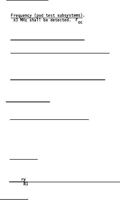
3.5.1.2.3.1
Any (and all) frequency(ie
a band of Foc
is a frequency which will be
specified in the contract.
3.5.1.2.3.2 Power level (pod test subsystem). The power level shall be
+5 dbm applied directly to the detector input a P1.
3.5.1.2.3.3 Sensitivity adjustment (pod test subsystem). When R6 is adj
to provide threshold sensitivity at +1 dbm for the Foc frequency, R36 sha
provide a sensitivity adjustment range of at least O to -10 dbm for the
frequency.
3.5.1.2.3.4 Detection indication (pod test subsystem). The detection
indication for the Foc frequency shall be identical to that for the Fov
frequency (see 3.5.1.2.2.4).
3.5.1.2.4 Self test subsystem. The electronics assembly shall contain s
test capability which tests the sweep circuit, the detector circuit and
battery condition as specified in 3.5.1.2.4.1 through 3.5.1.2.4.3.
3.5.1.2.4.1 Sweep circuit and detector circuit. When S2 is depressed, t
sweep voltage shall be generated and applied to the input of the detector
circuit, excluding the detector diode. The sweep voltage shall activate
detector circuit and cause indicator lamp DS-1 to flash with a period of
(+1, -.5) second and duty cycle of 10 to 25 percent during a portion of t
active sweep. The number of flashes per sweep period shall be a function
the adjustment of R6, R36, the battery voltage and sweep duration. The n
of flashes per sweep shall be 10 2 nominally, but may vary between 6 and
3.5.1.2.4.2 Battery test. When S1 or S2 is depressed, the DS-2 indicato
lamp shall flash with a period of 2 1 seconds and duty cycle of 10 to 2
percent when the battery voltage is 11.55 volts or above. It shall not fl
when the battery voltage is 11.50 volts or less.
3.5.1.2.4.3 Batte
condition indicator threshold adjustment. Adjustment
variable resistor,
Z, shall provide a battery condit ion indicator thres
range of at least 10.25 to 11.55 volts.
3.5.1.3 Plain shroud. The plain shroud shall be easily attachable/detac
to/from the electronics assembly. It shall be manufactured in accordance
Drawing 887AS400 and all documents listed thereon and shall meet all the
requirements of that drawing. The shroud shall provide protection for the
detector subsystem in the electronics assembly from high level electromagn
fields and shall absorb and attenuate RF energy radiated from the antenna
the unit under test. The shroud shall provide not less than 4 dB attenuat
of the RF signal which is radiated from the weapon during a weapon test.
|
|
Privacy Statement - Press Release - Copyright Information. - Contact Us |