 |
|||
|
Page Title:
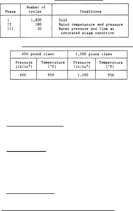
Table V. Pressure-temperature conditions for life cycle test |
|
||
| ||||||||||
|
|  MIL-V-24642(SH)
TABLE IV.
Life cycle test phases.
Pressure-temperature conditions for life cycle test.
TABLE V.
4.6.4.1 One life cycle from the trip position shall consist of the
following:
(a)
Reenergize the solenoid.
(b)
Rotate the handwheel clockwise to a stop position.
(c)
Latch the trip mechanism.
(d)
Fully open the valve by turning handwheel counterclockwise.
(e)
Energize the solenoid.
4.6.5 Hydrostatic pressure test. Each valve shall be subjected to an
internal pressure as specified in table III for a duration of 1 minute
(minimum). The water temperature shall not exceed 100F. Any weeping,
leakage, or permanent deformation shall be cause for rejection. The valve
shall be tested in the fully open position.
4.6.6 Seat leakage test. Each valve shall be pressurized in the direction
of flow and examined for seat tightness. Test pressures shall be in accordance
with table III. The testing medium shall be clean tap water with no additive
other than cutting oil at temperatures not less than 40F or more than 100F.
Duration of test shall be 1 minute (minimum). There shall be no visible signs
of leakage. Should there be any visible leakage, this test shall be continued
for the length of time required to accurately determine the rate of leakage.
Leakage shall not exceed 20 cubic centimeters per hour. The valve shall be
tested in the tripped closed position.
4.6.7 Gland exhaust leakage. The valves gland exhaust flange shall be
connected to a manometer with a graduated scale of 30 inches of water and a
vacuum system to meet the requirements as specified in 3.4.11.5,
4.7 Verification of material identification and control. Valves will
be used in critical shipboard systems. The use of incorrect or defective
material would create a high probability of failure resulting in serious
personnel injury, loss of life, loss of vital shipboard systems, or loss of the
14
|
|
Privacy Statement - Press Release - Copyright Information. - Contact Us |
