 |
|||
|
|
|||
| ||||||||||
|
|  MIL-V-81995/6(AS)
ATS Speed Signal Threshold. The speed signal inputs of the FSR shall be
balanced through appropriate switching for left or right activation. The
signal threshold (minimum amplitude required for operation) shall be as low as
possible, consistent with EMIC and BIT requirements. The threshold shall not
exceed 0.55 volts rms for a sine waveform at 1,000 Hz, and it shall not exceed
0.75 volts rms at 6,360 Hz due to input circuit filtering.
Input Impedance - Speed Sensor. The speed signal input impedance, when
selected, shall be greater than 1,400 ohms at 6,500 Hz. When not selected,
the input impedance shall exceed 10,000 ohms. Measurement shall be made at
room temperature.
Zero Speed Input. If a speed signal of not less than 1,000 Hz is not
sensed at 12 4 seconds, the FSR output shall be disabled.
ATS Speed Output. A buffered, conditioned speed signal shall be provided
at the FSR connector.
Zero Speed Shutoff. If the FSR, after energizing the crank switch holding
coil, fails to detect a speed signal of greater than 806 Hz, it shall
de-energize the crank switch holding coil after 12 4 seconds have elapsed.
FSR Output. The output shall be capable of continuously energizing the
crank switch holding coil. Rated coil hold-in voltage is 15 to 30 vdc.
Minimum coil resistance is 220 ohms at 20C.
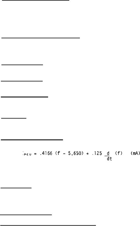
FSR Output Signal to PCU. The PCU output shall control current through the
PCU in accordance with the following characteristic equation:
where f = speed signal frequency modified by appropriate dynamic
response characteristics to provide optimum system response.
Start Signal. Electric power in conformance with MIL-STD-704, Category B,
will be supplied from engine start circuitry to the left crank or right crank
inputs of the FSR. Application of power shall initiate BIT. If no fault is
detected, nominal 28 vdc power shall be connected to the output.
Warm-Up Requirements.
No warm-up is allowed.
Ground Maintenance Mode Speed Control:
The ATSCV shall regulate ATS speed during ground maintenance operation
to 59 1% (100% = 16,810 rpm PTS speed) during all steady state conditions in
which the ATSCV is less than full open.
The maximum ATS speed during start-up and step load decreases shall not
exceed 64 percent.
4
|
|
Privacy Statement - Press Release - Copyright Information. - Contact Us |