 |
|||
|
|
|||
| ||||||||||
|
|  MIL-V-82440(OS)
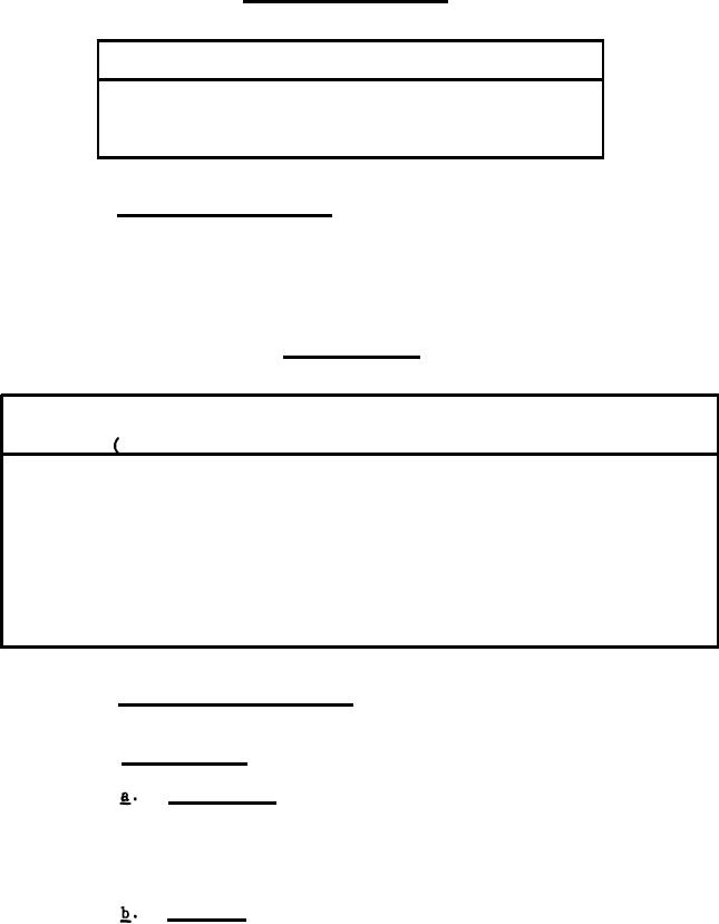
TABLE II
ACCELERATION SCHEDULE
Acceleration Direction
Magnitude (g 's 10%)
(See Figure 1)
Longitudinal axis, Fwd
25
Longitudinal axis, Aft
35
Shock, ready condition. The valve, mounted as shown in
3.4.3
Figure 1, shall be capable of meeting the performance requirements after
being subjected, in the ready condition, to the shock loads defined in Table
III . Shock is defined in 6.3.6.
TABLE III
.
SHOCK SCHEDULE
Direction of Number
Peak
Impact
Deceleration Of
Magnitude
Duration
Test
g's 10%)
Sequence
(ms)
Force
Axis
Impacts
Aft
0.5
to 1.5
Longitudinal
3
1
300
Optional
Transverse A
2
85
0.5
to 1.5
3
Optional
Transverse B
0.5
to 1.5
3
85
3
1800
to 20.0
Longitudinal
Fwd
4
45
3
Longitudinal
5
60
Aft
3
8.0
to 10.0
Longitudinal
Fwd
60
3
6
8.0
to 10.0
Optional
60
Transverse A
3
8.0
to 10.0
7
Transverse B
Optional
60
3
8
8.0
to 10.0
Temperature and humidity.
3.4.4
Non-operating.
3.4.4.1
Temperature. The valve shall be capable of meeting
the performance requirements subsequent to withstanding,
in the non-operating condition, environmental tempera-
tures between -45 F and +140 F. Temperature is defined
in 6.3.7.
Humidity. The valve shall be capable of meeting the
performance requirements subsequent to withstanding,
in the non-operating condition, an environment of at
least 95 percent relative humidity at +110 F for a
4
minimum period of 8 hours. Humidity is defined in 6.3.8.
|
|
Privacy Statement - Press Release - Copyright Information. - Contact Us |
