 |
|||
|
|
|||
| ||||||||||
|
|  MIL-W-15805F(SHIPS)
and angle deck. These outputs shall be capable of
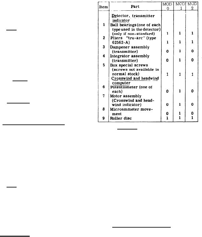
Table I - Onboard repair parts required per ship.
driving a total of five indicators. The signals from
the wind direction and speed transmitter shall be
received by type lHCT synchros, in accordance with
MIL-S-2335. The servo amplifier shall be a solid
state device.
3.4.5.1 S i z e - The crosswind-headwind com-
puter shall be as small and lightweight as practical,
but in no case shall the dimensions and weight ex-
ceed the following:
Height - 13 1/2 inches
Width - 15 1/2 inches
Depth - 7 1/2 inches
Weight -35 pounds
( Figure 7 is provided for guidance only)
3.4.5.2 Accuracy - The crosswind-headwind
computer shall resolve the input signal so that the
accuracy of the output signal voltage shall be within
1 knot of the theoretical computed value.
3.4.5.3 Sensitivity .- When the input signal is
changed instantaneously from 0 to 60 knots the out-
put signal shall reach this value in a time not to ex-
ceed 12 seconds.
3.4.6 Crosswind-headwind indicator. - The
3.4.8 Drawings .- Drawings shall be furnished
crosswind-headwind indicator shall be manufactured
in accordance with MIL-D-963 class A, shop or
in accordance with Drawing 3331265. The crosswind-
manufacturing type drawings are required. `The
indicator shall be contained in a watertight enclosure
following information shall supplement the drawing
designed for bulkhead mounting two voltmeters made
information requirements currently specified under
in accordance with MIL-M-16034, and which shall
MIL-D-963:
have an accuracy of 1 percent. The upper voltmeter
shall be calibrated 30 to 0 to 30 knots crosswind, and
(a) Power requirements under full load and
the lower voltmeter shall be calibrated 0 to 60 knots
standby conditions.
headwind. Red dial illumination with a rheostat to
(b) Heat dissipated under full load and stand-
vary the intensity shall be provided. Two pilot lights
by conditions.
shall serve to indicate whether the dials read straight
(c) Voltage and resistance readings at key
or angle deck values.
service points.
(d) All parts in correct relation as to physical
3.4.6.1 Size. - The crosswind-headwind indicator
location with terminals clearly shown
shall be as small and lightweight as practicable, but
with markings and all wiring between
in no case shall the dimensions and weight exceed
parts.
the following:
(e) The center of gravity shall be shown for
each piece of parent equipment.
Height - 13 3/4 inches
Width - 7 1/2 inches
4. QUALITY ASSURANCE PROVISIONS
Depth -6 1/2 inches
Weight -24 pounds
4.1 Responsibility for inspection. - Unless
(Figure 8 is provided for guidance only).
Otherwise specified in the contract or purchase
order, the supplier is responsible for the perform-
3.4.7 Repair parts. - Repair parts and applicable
ance of all inspection requirements as specified
repair parts lists required for maintenance of the
herein. Except as otherwise specified, the sup-
parent equipment shall be in accordance with Draw-
plier may utilize his own facilities or any commerc-
ing 3331240. The items and quantity of each, re-
ial laboratory acceptable to the Government. The
quired for onboard repair parts shall be as shown
Government reserves the right to perform any of.
in table 1.
7
|
|
Privacy Statement - Press Release - Copyright Information. - Contact Us |
