 |
|||
|
Page Title:
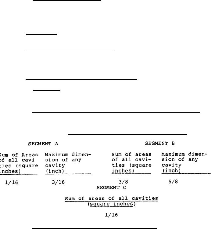
Table I. Maximum cavity areas and dimensions. |
|
||
| ||||||||||
|
|  MIL-W-50986A (AR)
2.1.3 Order of precedence. In the event of a conflict
between the text of this specification and the references cited
herein, the text of this specification shall take precedence.
3.
REQUIREMENTS
3.1 Material. Material shall be in accordance with the
applicable drawings and specifications.
3.2 Components and assemblies. The components and assemblies
shall comply with all requirements specified on drawing (dwg)
9258192 and associated drawings and with all requirements
specified in applicable specifications and standards.
3.3 Cavitation and explosive leakage.
3.3.1 General. Cavities having a maximum (max) projected
dimension of 1.32 inch or less shall be disregarded provided that
they are separated by 1/2 inch of solid explosive.
3.3.2 Maximum projected area and dimensions of cavities. The
maximum projected areas dimensions of cavities in each of the
segments (see figure 1) shall be in accordance with Table I.
Maximum cavity areas and dimensions.
TABLE 1.
3.3.3 Cavities extending into two segments. The projected
area of cavities extending into two segments shall meet the
requirement of both segments.
3
|
|
Privacy Statement - Press Release - Copyright Information. - Contact Us |
