 |
|||
|
|
|||
| ||||||||||
|
|  MIL-A-19401(Aer)
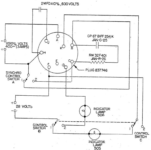
4.3.3.2.1.5.1 With control switches A, B, and C in posi-
tion 2, the indicator lamp, 506, Figure 1, shall light
when the straight lever is moved 0.125 .005 inch towards
the nameplate.
4.3.3.2.1.5.2 With the control switches A, B, and C in
position 2, the indicator lamp, 506, shall not light when
the straight lever. is moved O.125 .005 inch in a direction
away from the nameplate.
Figure 1. Test Control Circuit
8
|
|
Privacy Statement - Press Release - Copyright Information. - Contact Us |
