 |
|||
|
|
|||
| ||||||||||
|
|  MIL-A-21001A(Wep)
4.5.3.6 Shunt contact resistance. Attach a short lead wire whose
resistance is less than 0.03 ohm to each prong of a dummy actuator (4.4.1)
and insert the actuator in one of the recesses in the shutter. Assemble
the shutter to the contact mount assembly and rotate it between the shunt
fingers. Apply the test probes of an ohmmeter to the leads from the
actuator. Repeat this test with the same dummy actuator inserted in the
other recess of the shutter.
4.5.3.7 Contact mount assembly. This test is performed on the contact
mount assembly, Dwg 883562. Apply the test probes of an ohmmeter (4.4.4)
to the two terminal pins.
4.,5.3.8 Dielectric test.
On the contact mount assembly apply the test
probes of a megohmmeter
4.5) between either terminal pin and the rivets
of the shunt fingers. Then assemble the shutter and contact mount assembly
in the housing, without actuators and without the safety spring. Measure
the insulation resistance between each terminal pin and the shutter shaft,
and between each terminal pin and the housing.
4..6 Preproduction and periodic production tests
4.6.1 Vibration.
The mechanism shall be tested in two conditions, as
described below.
(a) The first condition shall be with the arming device mounted
rigidly to the vibration table by means of a mounting method simulating
the actual method of mounting used in service. The vertical displacement
component of the vibration shall be simple harmonic motion. The samples
shall be placed on the vibration table so that equal quantities of
devices experience vibration perpendicular to the plane of mounting and
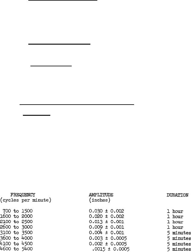
vibration parallel to the plane of mounting. The mechanism shall be
vibrated through a range of frequencies from 700 to 5400 cycles per minute
in 100 cycles per minute increments. The duration of the vibration of
each increment and the, amplitude of the vibration shall be in accordance
with the following schedule:
8
|
|
Privacy Statement - Press Release - Copyright Information. - Contact Us |
