 |
|||
|
|
|||
| ||||||||||
|
|  MIL-C-11015E
(e) Final measurements - After the final cycle, capacitors shall be conditioned at 25 C 5 C and a relative
humidity of 30 percent to 60 percent for a period of 18 hours minimum, 24 hours maximum, and shall be
visually examined for mechanical damage. Dielectric withstanding voltage (when specified, see 3.1),
insulation resistance, and capacitance (when specified, see 3.1) shall be measured as specified in 4.7.2.1,
4.7.4, and 4.7.5, respectively.
4.7.13 Solderability (see 3.16). Capacitors shall be tested in accordance with method 208 of MIL-STD-202. The
following detail shall apply:
(a) Number of terminations of each part to be tested - As specified (see 3.1).
4.7.14 Resistance to soldering heat (all styles except CK22, CK27, CK75, CK79, and CK85) (see 3.17).
Capacitors shall be tested in accordance with method 210 of MIL-STD-202. The following details and exceptions
shall apply:
(a) Surface oxides and dross shall be skimmed off the solder pot immediately before lead immersion to ensure
full and complete heat flow through the leads.
(b) Depth of immersion in molten solder - To a minimum of .050 inch, +.020, -0 inch (1.27mm, +0.51, -0mm)
from the capacitor body (the example shown in figure X is applicable to all terminal types).
(c) Test condition letter - B, except that the immersion duration shall be 20 seconds 1 second.
(d) Cooling time prior to measurement after test - 10 minutes 1 minute, unless otherwise specified (see 3.1).
(e) Measurements after test - Capacitance, dissipation factor, and insulation resistance at 25 C shall be
measured as specified in 4.7.4, 4.7.5, and 4.7.6, respectively.
(f)
Internal examination after test - Not required.
4.7.15 Voltage-temperature limits (see 3.18).
4.7.15.1 For qualification inspection. Capacitors shall be tested as specified in 4.7.5, except that the capacitance
measurements shall be made at the steps shown in table VIII and at a sufficient number of intermediate points
between steps B and G of table VIII to establish a true characteristic curve. The capacitance value obtained in step
C of table VIII shall be considered as the reference point. The capacitance measurement at each temperature shall
be recorded when two successive readings taken at 5-minute intervals at that temperature indicate a capacitance
change of less than 1 percent.
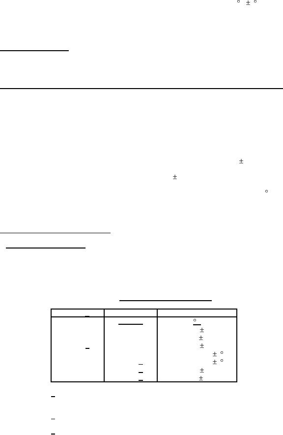
TABLE VIII. Voltage-temperature-limit cycle.
Step
1/
Voltage
Temperature
volts, dc
C
A
None
+25 2
B
None
-55 2
C 3/
None
+25 2
D
None
Max rated temp 2 C
E
500 2/
Max rated temp 2 C
F
500 2/
+25 2
G
500 2/
-55 2
1/ For styles CK05 and CK06 capacitors with dual temperature
ratings (see 3.1), steps D and E shall be performed at each
maximum rated temperature.
2/ For capacitors with voltage ratings of less than 500 volts,
rated voltage (see 3.1) shall be applied.
3/ Reference point.
14
|
|
Privacy Statement - Press Release - Copyright Information. - Contact Us |
