 |
|||
|
Page Title:
Figure 1. Critical cartridge dimensions |
|
||
| ||||||||||
|
|  MIL-C-24224B(SH)
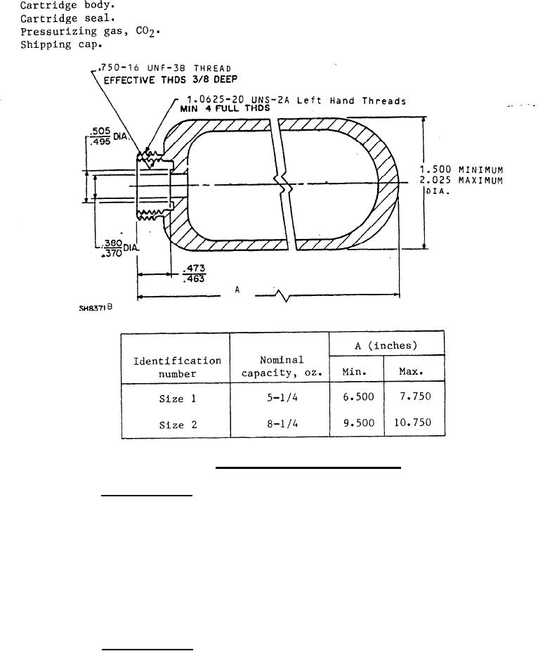
Critical cartridge dimensions.
FIGURE 1.
3.2.1 Cartridge body. The cartridge body shall be constructed by a process
suitable for the intended use. One end shall be necked down or provided with a
separate adapter and machined with an external 1.0625-20 UNS-2A-LH thread for
attachment to the extinguisher. The neck or adapter shall also have an internal
.750-16 UNF-3B thread with a minimum of six threads to receive the cartridge seal.
Critical cartridge thread section dimensions shall be as shown on figure 1.
Threads shall be in accordance with FED-STD-H28 and FED-STD-H28/2.
3.2.1.1 The external neck thread may be American National Thread Form
1.0625-20 NS-2 left hand thread for gas cartridges having passed first article
testing prior to 1 January 1985.
3.2.2 Cartridge seal. The cartridge seal body shall be formed of brass
with an external .750-16 UNF-3A thread to fit into the cartridge neck, Each seal
assembly shall be furnished as a unit for recharging purposes and shall consist
of the body, bushing, seal disc and baCkup washer.
4
|
|
Privacy Statement - Press Release - Copyright Information. - Contact Us |
