 |
|||
|
Page Title:
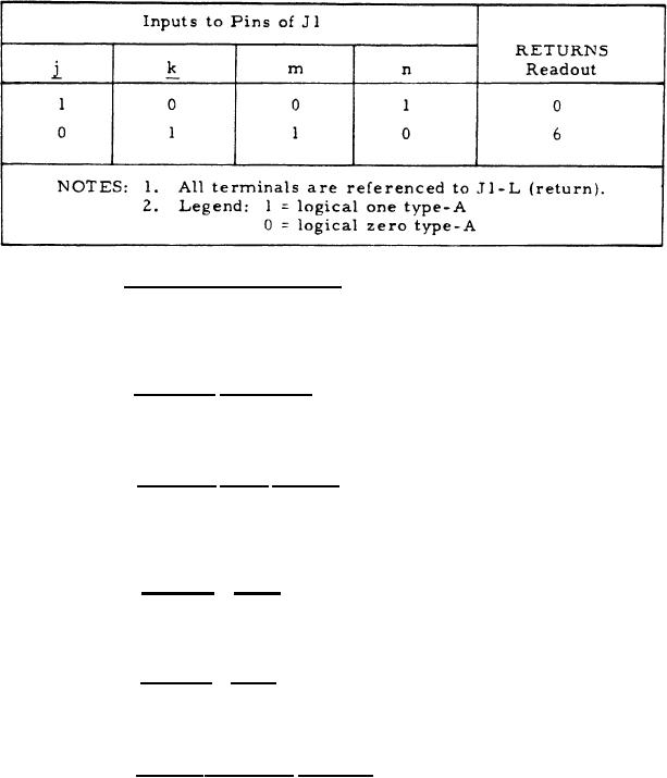
Table IV. Returns Readout Selection Logic |
|
||
| ||||||||||
|
|  MIL-C-50734(MU)
8 August 1973
TABLE IV
RETURNS READOUT SELECTION LOGIC
3.3.1.9 Range indicator drive. With the logical one digital type-A
signal (item 3.1) of table I applied to J1-R, the voltage at J1-N shall be
+15.0 1.0 Vdc. With the logical zero type-A signal (item 3.1) of table I
applied to J1-R, the voltage at J1-N shall be +0.4 0.4 Vdc.
3.3.1.10 Readout blanking. With the logical zero digital type-A
signal (item 3.1) of table I applied to J1-y, the range readout shall be
blanked momentarily.
3.3.1.11 M a n u a l reset signal. With no signal applied to Jl-T,
the voltages at J1-V and J1-U shall each be +4.2 1.0 Vdc. With the
logical zero digital type-A signal (item 3.1) of table I applied to J1-T,
the voltages at J1-V and J1-U shall each be +0.2 0.2 Vdc.
3.3.1.12 Turn-off reset.
The time interval between turn-off of
the + 15 Vdc power (item 2. 3) of table I and the change in level of the
T
voltages at J1-V and JI-L shall be as shown in figure 1.
3.3.1.13 Turn-on reset.
The time interval between turn on of the
+15 Vdc power (item 2.3) of table I and the change in level of the voltages
at J1-V and J1-U shall be as shown in figure 2.
3.3.1.14 M A L F indicator disable. With the digital type-A signal
(item 3.1) of table I applied as specified in table VI, the response of the
MALF indicator shall be as specified in table VI.
7
|
|
Privacy Statement - Press Release - Copyright Information. - Contact Us |
