 |
|||
|
Page Title:
Malfunction logic and light drive |
|
||
| ||||||||||
|
|  MIL-C-50735(MU)
8 August 1973
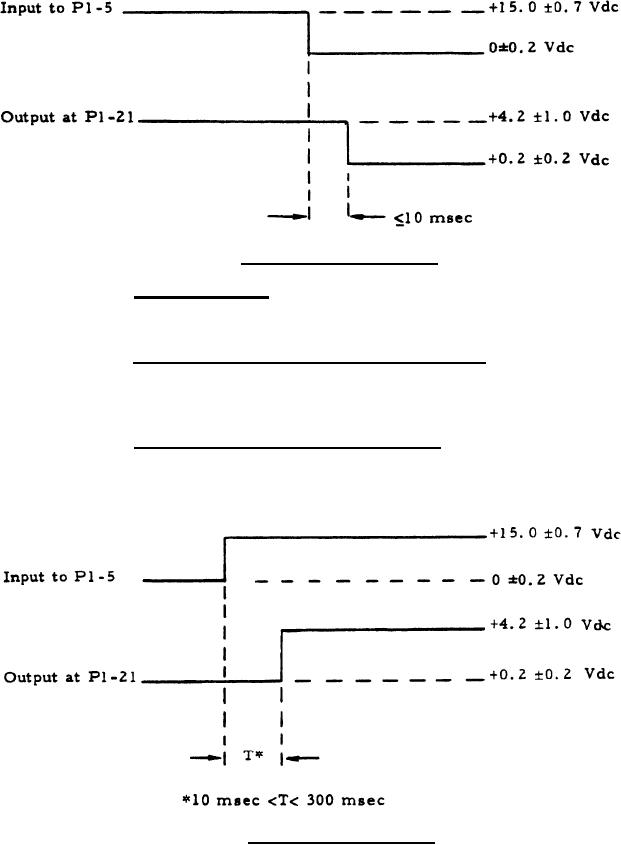
Figure I. Turn-off
Reset
Time
3.3.1.4 Turn-on reset. The time interval between turn-on of
the +15 Vdc power (item 2.2) of table I of P1-5 and the appearance of the
reset voltage at P1-21 shall be as shown of figure 2.
3.3.1.5 First-second-last logic and light drive. With the logical
zero digital type-A signal (item 3.1) of table I applied as specified in table
II, the voltages at the output terminals shall be as specified in table II for
the associated input conditions.
3.3.1.6 Malfunction logic and light drive. With the digital type.
A signal (item 3.1) of table I applied as specified in table III, the voltage
at the output terminals shall be as specified in table III for the associated
i n p u t conditional.
Figure 2. T u r n - o n
Reset
Time
5
|
|
Privacy Statement - Press Release - Copyright Information. - Contact Us |
