 |
|||
|
Page Title:
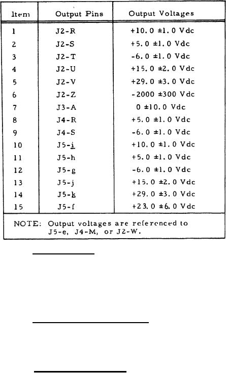
Table II. Primary Power Application Response |
|
||
| ||||||||||
|
|  MIL-C-50743(MU)
8 August 1973
TABLE II
PRIMARY
POWER APPLICATION
RESPONSE
3.3.1.3 Range readout. With the range data output generation
circuit (item 4.2 of table I) substituted for the Circuit Card Assembly:
10559305 (Counters), closing the switches one at a time, shall cause
the range indicated on the signal line indentified with the closed switch
on figure 3 to be displayed on the Circuit Card Assembly: 11737350
(Readout).
3.3.1.4 Target selection and reset, With J1-j connected to
J1-e and J1-f connected to J1-g and with the input conditions of
items I through II of table III established in the item number order,
the J1 outputs and the range readouts shall be as specified in table III.
3.3.1.5 Minimum range inhibit (2), With J1-j connected to
Jl-e and J1-f connected to J1-k, with the logical on type-B signal
of table I applied to 31-h, J1-AA, and J2-h, with the logical zero
type-B signal of table I applied to J1-q, Jl-g, and J1-z, and with
switch S1 (on the Reply Gating Circuit Card Assembly: 10559295)
not depressed, the output at J2-f shall be as shown on figure 4.
8
|
|
Privacy Statement - Press Release - Copyright Information. - Contact Us |
