 |
|||
|
Page Title:
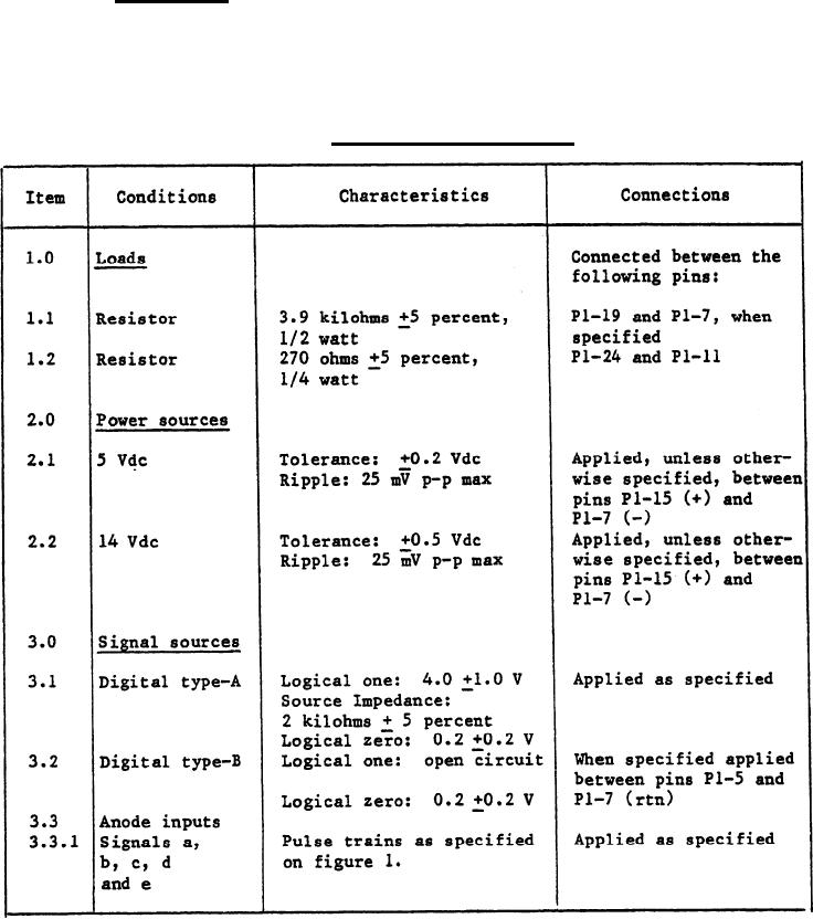
Table 1. Loads, power and signals. |
|
||
| ||||||||||
|
|  MIL-c-62202B(AR)
3.3.2 Lamp driver. With the load (item 1.1) of table I applied and with
the digital type-B signal (item 3.2) of table I applied at the logical zero
level, the output voltage between pins P1-19 and P1-7 shall be 13.0 1.0 volts
direct current (Vdc). With the digital type-B signal applied at the logical
one level, the voltage between pins P1-19 and P1-7 shall be 11.0 1.5 Vdc.
(See 4.6.1.2)
TABLE 1. Loads, power and signals.
4
|
|
Privacy Statement - Press Release - Copyright Information. - Contact Us |
