 |
|||
|
Page Title:
Table II. Readout selection logic. - Continued |
|
||
| ||||||||||
|
|  MIL-C-62202B(AR)
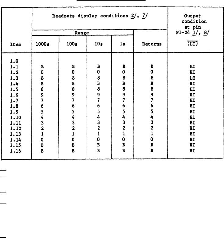
TABLE II. Readout selection logic. - Continued
1/ Signal condition voltages are referenced to pin P1-7
2/ Input and output terminal legend:
LTC is Lamp test control,, RBI is Ripple blanking input; LT is Lamp test.
3/ Input signal condition legend:
Signals a, b, c, d and e are anode input signals, item 3.3.1 of table I.
4/ Input signal condition legend:
a. NC = no connection
b. 1 = logical one digital type - A signal, item 3.1 of table I
(4.0 1.0)
c. 0 = logical zero digital type - A signal, item 3.1 of table I
(0.2 0.2)
5/ Input signal condition legend:
a. 1 = logical one digital type - B signal, item 3.2 of table I
(open circuit)
b. O = logical zero digital type - B signal, item 3.2 of table I
(0.2 0.2)
7
|
|
Privacy Statement - Press Release - Copyright Information. - Contact Us |
