 |
|||
|
|
|||
| ||||||||||
|
|  MIL-C-82631(OS)
at a table vibratory amplitude of 0.003 +0.000 -0.001 inch. The change
in frequency shall be made in 1-Hz steps and maintained at each step for
15 5 seconds. The frequencies at which the greatest reasonance or dis-
continuities in excess of 100 microseconds occur shall be noted.
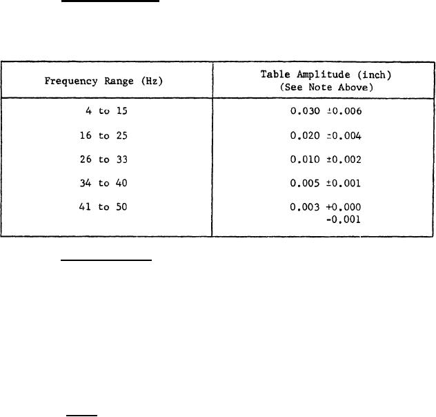
(b) Vibration levels. The sample shall be vibrated in accordance
with Table IV. The dwell time at each interal frequency shall be 5
minutes.
TABLE IV
(c) Resonance dwell. The sample shall be vibrated for 2 hours at
the frequency at which the greatest resonance or discontinuities were
noted. If no discontinuity or resonance occurred during the search, this
test shall be performed at 50 Hz. During the resonance search and dwell
portions of the test, hydrostatic pressure shall be applied for 5 minutes.
The pressure shall be equal to normal depth firing conditions.
4.5.4.2.2 The above schedule shall be completed in each of the three
mutually perpendicular axes. At the conclusion of the vibration tests,
the test specimens shall be subjected to the tests of 4.5.3.2 (Insulation
resistance) and 4.5.3.3 (Continuity). Immediately following the above
tests, the hydrostatic pressure test of 4.5.4.1 shall be performed.
4.5.4.3 Shock. The cable connector shall be mated to Torpedo Control
Cable Mk 7 Mod 0 and securely mounted to a shock fixture simulating ser-
vice conditions as shown in Figure 4. All circuits shall be wired in
series for the purpose of monitoring any discontinuities. The test speci-
mens shall be subjected to the shock test defined in MIL-S-901 for light-
weight equipment. Three shocks shall be applied parallel to each of the
three principal axes shown in Figure 4. In each axis, the hammer shall
11
|
|
Privacy Statement - Press Release - Copyright Information. - Contact Us |
