 |
|||
|
Page Title:
Figure 1. Dimensions and configuration - Continued |
|
||
| ||||||||||
|
| 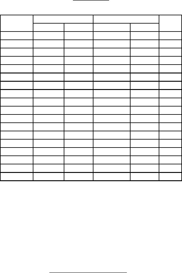 MIL-C-83522/16B
w/AMENDMENT 1
Millimeters
Inches
Letter
Notes
Min
Max
Min
Max
A (SM/MM)
2.4985
2.4995
0.09837
0.09841
3
A (MM)
2.498
2.500
0.0983
0.0984
3
B
5.25
5.38
0.207
0.212
C
0.91
1.07
0.036
0.042
D
7.06 min
0.278 min
E
7.75
8.00
0.305
0.315
F
2.56
4.50
0.101
0.177
G
0.58
0.89
0.023
0.035
H
1.60 min
0.063 min
J
9.40
9.80
0.370
0.386
L
2.00
2.00
0.079
0.079
4
M
0.64
1.12
0.025
0.044
N
8.56 min
0.337 min
5
Q
1.04
1.60
0.041
0.063
R (SM/MM)
8
25
0.3
1.0
6
R (MM)
8 min
0.3 min
6
X (SM/MM)
0.020
0.063
0.0008
0.0025
7
X (MM)
0.000
0.063
0.0000
0.0025
7
NOTES:
1. Dimensions are in millimeters.
2. Inch equivalents are given for general information only.
3. Use A (SM/MM) for single mode applications. Use A (SM/MM) or A (MM)
for multimode applications.
4. L dimension is the diameter of a circle on the surface of the ferrule
that is concentric with the axis of the ferrule.
5. Design optional.
6. R dimension is for reference or conceptual design considerations
only. This dimension is the radius of the end of the ferrule when
the surface of the ferrule is spherical, and L is as given.
7. X dimension is the distance that the apex of the end of the ferrule
extends beyond the circle described in note 4.
8. α angle to be between 20 and 35.
FIGURE 1.
Dimensions and configuration - Continued.
3
|
|
Privacy Statement - Press Release - Copyright Information. - Contact Us |
