 |
|||
|
Page Title:
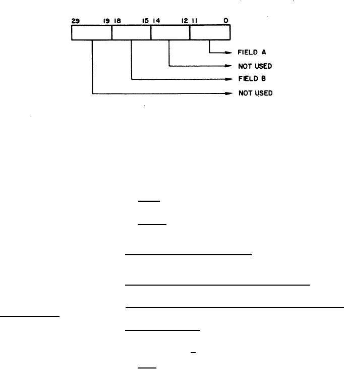
Figure 1. Format of Input Word to Computer from Digital Input Multiplexer |
|
||
| ||||||||||
|
|  MIL-D-81347C(AS)
Format of Input Word to Computer from Digital Input Multiplexer
Figure 1.
(1) Field A - represents the data bits from the peripheral equip-
ment being serviced by the DIM.
(2) Field B - represents the address of the peripheral equipment
selected by the DIM. The functional flow diagram (Figure 2) indicates the DIM channel assignments
for the peripheral equipments.
Digital Input Multiplexer to Computer - Communications between
3.5.1.4.1.5.2
the computer and the DIM shall be in accordance with Appendix I. D a t a transfer is accomplished by
the Input Data Request/Input Acknowledge scheme.
Digital Input Multiplexer to Maintenance Control Panel - Commu-
3.5.1.4.1.5.3
nications between the Maintenance Control Panel and the DIM shall be in accordance with 3.5.1.4.9.
Peripheral Equipments Contained Within Logic Unit 1 and Digital
3.5.1.4.1.5.4
Input Multiplexer.
Signal
Characteristics
3.5.1.4.1.5.4.1
(1) logical "1" = +5 1.5 volts
logical "0" = 0 + 1/2 -0.0 volts
(2) Enter - The Enter line from a peripheral equipment shall
change from a logical "1" to a logical "0" when new data is available. The Enter line shall remain
stable for a minimum of 20 milliseconds or until a Channel Input Acknowledge signal is recieved from
the DIM.
19
|
|
Privacy Statement - Press Release - Copyright Information. - Contact Us |
