 |
|||
|
|
|||
| ||||||||||
|
|  MIL-D-81347C(AS)
3.5.1.4.5.2
General Description - The Pilot Keyset/CRT Tray/Ordnance
Panel Logic Subunit (hereafter referred to as Logic Subunit) shall provide:
(1) The encoding and transmission of data from the Pilot Keyset
or the CRT Tray or the Ordnance Panel to the computer.
(2) The decoding and storage of data from the computer to the
Pilot Keyset or the CRT Tray or the Ordnance Panel.
Operating Requirements - The Logic Subunit shall detect the
3.5.1.4.5.3
depression of any switch on the associated device (Pilot Keyset or CRT Tray or Ordnance Panel) and
transmit a code identifying the depressed switch to the computer via the DIM. The operator shall not
have two switches depressed at the same time.
The Logic Subunit shall interpret the computer output word re-
ceived from the DOM and perform one of the following operations:
(1) Selectively store bits 0 - 4 of the output word in one of five
storage registers
(2) Reset the five storage registers
(3) Enable one of the test loops contained in the Logic Subunit
Each Logic Subunit shall be self initializing; i. e. , when power s
applied to the Logic Subunit, no spurious data shall be transmitted to the DIM and the Logic Subunit
shall be ready for normal operation.
Test Loops - Test loops shall be designed into each Logic Subunit.
3.5.1.4.5.4
The test loops shall permit the computer program to exercise the Logic Subunit and monitor the per-
formance for possible logic malfunctions. The test loops shall be comprehensive; i. e. , the test loops
shall exercise every logic element in the Logic Subunit in all of its functions insofar as possible. The
test loops shall be utilized for in-flight performance monitoring (IFPM) and diagnostic programs.
Interface Requirements - Refer to the functional flow diagrams
3.5.1.4.5.5
for the Pilot Keyset, CRT Tray and Ordnance Panel Logic Subunits (Figures 19, 20 and 21).
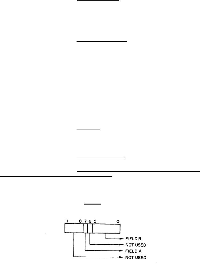
Format of Input Word to Digital Input Multiplexer from Pilot
3.5.1.4.5.5.1
Keyset or CRT Tray or Ordnance Panel Logic Subunit - Refer to Figure 13.
(1) Field A - Identifies test loop operation data; i.e. , if bit 7 is
a logical "l", the data contained in the remainder of the input word is not the result of a switch de-
pression but is due to test loop operation of the Logic Subunit by the computer program.
(2) Field B - Identifies the switch depressed or contains the data
resulting from test loop operation.
Figure 13. Format of Input Word to Digital Input Multiplexer from Pilot Keyset, CRT Tray;
or Ordnance Panel Logic Subunit
46
|
|
Privacy Statement - Press Release - Copyright Information. - Contact Us |
