 |
|||
|
Page Title:
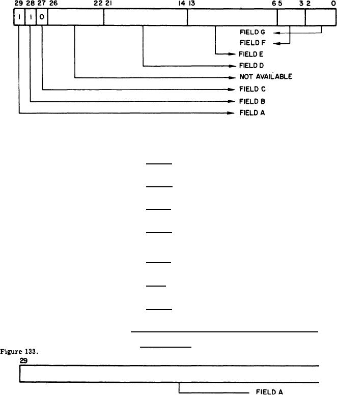
Figure 133. Format of Peripheral OA Word |
|
||
| ||||||||||
|
|  MIL-D-81347C(AS)
Format of DMS Status EI
Figure 132.
Field A - Bit 29 - EI Identifier bit and for this EI It shall
always equal one.
Field B- Bit 28 -DMS EI Idenifiier bit and for this EI it shall
. always equal one.
Field C - Bit 27-Power monitor identifier bit and for this
El it shall always equal zero.
Field D - Bits 21 through 14- Status of IDR Monitor EI
enable code in the DMS. (Refer to the IDR Monitor EI Enable Code Table in 3.5.4.4.1.6. 2(4),
Field E.)
Field E - Bits 13 through 6 - Status of Peripheral EI enable
code in DMS. (Refer to the Peripheral EI Enable Code Table in 3.5.4.4.1.6. 2(4), Field F.)
Field F - Bits 5 through 3 - Status of Output select code in
the DMS. (Refer to the Output DMS Channel Select Code Table in 3.5.4 .4.1.6.2 (4), Field G.)
Field G - Bits 2 through 0 - Status of input select code in the
DMS. (Refer to the Input DMS Channel Select Codes Table in 3.5.4.4.1.6.2(4), Field H.)
Format of Output Words from the Computer to the DMS
3.5.4.4.1.6.2
(1) Peripheral OA - Refer to the word format shown in
Figure 133.
Format of Peripheral OA Word
Field A - Bits 29 through 0 - will represent the data bits
from the computer via the ODR/OA data transfer mode to the peripheral equipment being serviced by
the selected DMS channel.
235
|
|
Privacy Statement - Press Release - Copyright Information. - Contact Us |
