 |
|||
|
Page Title:
Data Multiplexer Subunit to Computer |
|
||
| ||||||||||
|
|  MIL-D-81347C(AS)
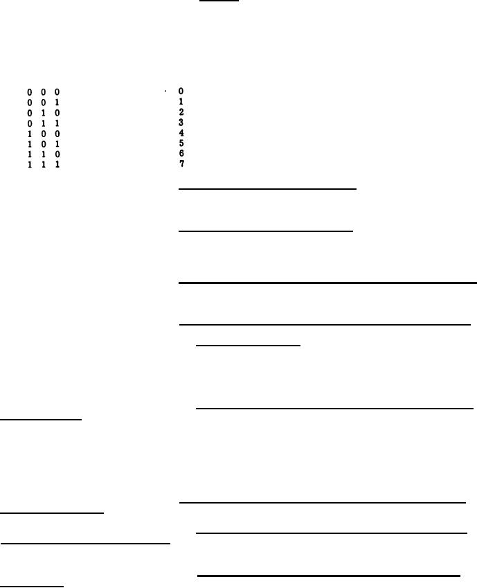
Field H - Bits 2 through 0- The DMS shall when instructed
in Field C select one of the DMS Input Channels to send IDR/IA input data to the computer in accord-
ance with the following tabulation:
INPUT DMS CHANNEL SELECT CODES
BIT
AIRCRAFT PERIPHERAL
DMS CHANNEL NUMBER
210
DMS Loop Test
Input DM Channel
Auxiliary Display Logic
Input DM Channel
Input DM Channel
Input DM Channel
Input DM Channel
Input DM Channel
Data Multiplexer Subunit to Computer - Communications be-
3.5.4.4.1.6.3
tween the DMS and the computer shall be in accordance with Appendix I. Data transfer shall be ac-
complished by the Input Data Request/Input Acknowledge scheme and by the External Interrupt scheme.
Computer to Data Multiplexer Subunit - Communications between
3.5.4.4.1.6.4
the computer and the DMS shall be in accordance with Appendix I. Data transfer shall be accomplished
by the Output Data Request/Output Acknowledge scheme and by the External Function Request/External
Function scheme.
Data Multiplexer Subunit to and from Maintenance Control Panel -
3.5.4.4.1.6.5
Communications between the Maintenance Control Panel and the DMS shall be in accordance with
3.5.14.9.
Peripheral Equipments (External Interface Logic) and the DMS -
3.5.4.4.1.6.6
(1) Signal Characteristics - shall be in accordance with
Appendix 11 and WR-101, Section IL
(2) All signals between these peripherals and the DMS shall be
transmitted over twisted wire pair cables.
(3) DMS Channel Control Functions (EI, IDR, EFR, ODR, EIE,
IA, E F and OA). These signals shall be transferred between these equipments per Appendix I if the
peripheral device is being serviced by the selected DMS channel. If the DMS channel is not selected,
these signals shall be transferred per Appendix I as modified by 3.5.4.4.1.3 with respect to com-
munications with DMS channels not selected.
.
(4) Data, Input and Output shall be in accordance with Appendix
I as modified by 3. 5.4.4.1.3 as to bit quantity.
Peripheral Equipments (Internal Interface Logic) and the DMS
3.5.4.4.1.6.7
Signal Characteristics
(1) DMS Channel Control Functions EI, IDR, EFR, ODR, EIE
IA, EF, OA and Output Data Signals - same as 3.5.4 .4.1.6 . 6(3) and (4) - Output data to these DMS
channels shall be transmitted from the MCP.
(2) Spare 1 Test, Spare 2 Test, Spare 3 Test, Spare 4 Test,
Spare 5 Tests - Transmitted from the DNB for future expansion.
239
|
|
Privacy Statement - Press Release - Copyright Information. - Contact Us |