 |
|||
|
Page Title:
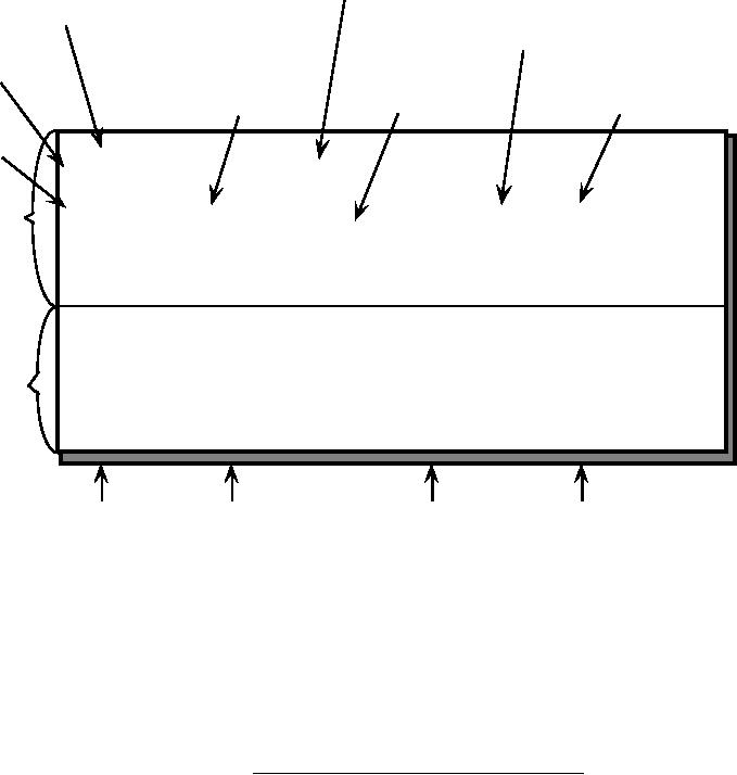
Figure 2. VPF physical record structure. |
|
||
| ||||||||||
|
|  MIL-D-89009
Documentation file name
(dash when no file present)
Header
length
Value description table
(dash when not applicable)
Table
Column definition
description
(Field type, number of
Column
Thematic index name
elements, key type)
description
(dash when not applicable)
Column
name
{4 Byte int};\
Drainage Areas;
DNAREA.DOC;\
Header
ID
=
I,1,P,
Row ID,
-,
-,:\
definition
DNPYTYPE=
I,1,N,
Type of Drainage Area,
INT.VDT,-,:\
TILE_ID =
S,1,F,
Tile Reference Identifier, -,
DNAREA.ATI,:\
FAC_ID =
I,1,F,
Face Primitive Foreign Key,-,
-,:;
1
4
176
1
2
3
143
2
Table
3
4
155
3
values
:
:
:
:
n
n
n
n
FAC_ID
ID
DNPYTYPE
TILE_ID
NOTES:
1.
The header portion (top half of the illustration) defines the entries
required for the VPF table header, while the content portion (bottom
half) defines the record entries for the data fields.
2. The backslash character (\) at the end of each line is used to indicate
that the record entry is continued uninterrupted to the next line; no
carriage returns should be embedded in the string.
3.
The semi-colon character (;) at the end each line is used to indicate the
end of the component.
4.
The colon character (:) at the end each line is used to indicate the end
of the column definition.
FIGURE 2.
VPF physical record structure.
11
|
|
Privacy Statement - Press Release - Copyright Information. - Contact Us |
