 |
|||
|
Page Title:
Table I. Testing and inspection - Cont'd |
|
||
| ||||||||||
|
|  MIL-E-1/188H
TABLE I. Testing and inspection - Continued.
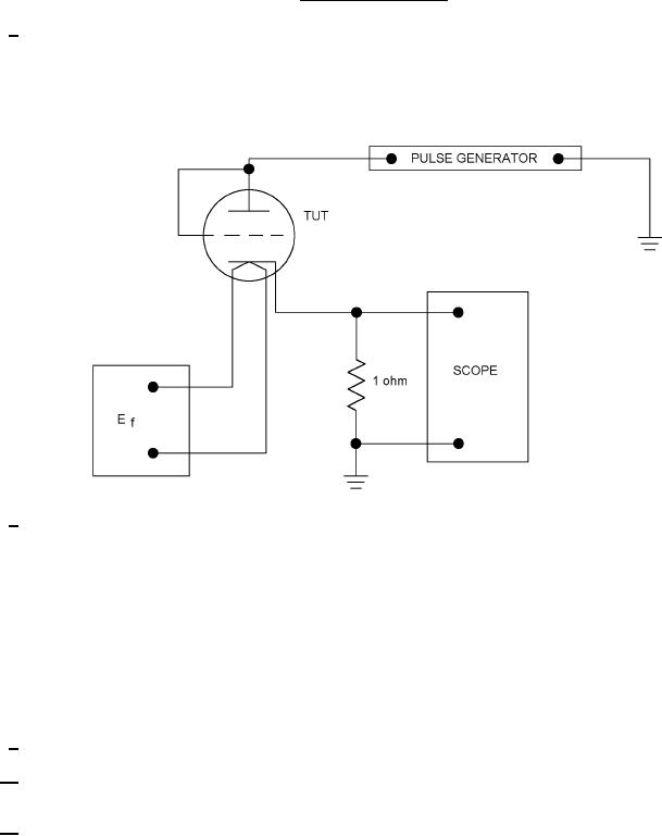
The pulse is essentially a square wave with 1.0-s rise time and 0.8-s fall. The pulse shall be applied to
7/
anode and grid tied together. Pulse emission shall be measured in terms of voltage, developed across a 1.0-
ohm resistor in the cathode circuit. Limit shall be tested as measured by the leading edge of a calibrated
oscilloscope trace, the amplitude of the trailing edge of which shall not vary by more than 20 percent from the
value of the leading edge.
8/
The grid pulse shall be a square wave meeting the pulse shape requirements of method 1296, and in addition,
the maximum amplitude shall occur within the first 20 percent of tp, tp = 10 s, and prr = 1,000 pps. The pulse
shall be applied to the grid by means of a driving circuit which produces the specified peak pulse voltage
directly at the grid terminal with respect to the cathode. Grid resistance, not exceeding 50 ohms, may be
inserted to prevent oscillation, provided readjustment of grid drive is made to maintain the specified pulse
amplitude directly at the grid terminal.
Peak currents shall be measured by means of a high-impedance oscilloscope, or equivalent device, connected
across a cathode resistor of 1.0 0.01 ohm. The specified limit refers to the maximum of the pulse amplitude.
The variation of the output pulse amplitude between 20 and 80 percent tp shall not exceed the specified limits
for Ćik(tp). Peak cathode current shall be read after 10 seconds or in the case of slumping peak cathode
current, when a stable reading is obtained.
9/
Leads may be clipped for application of voltages during impact.
10/
A grid resistor of 0.1 megohm shall be added to each section, except when a thyratron-type short indicator is
used.
11/
Envelope temperature (TE) requirements, when measured in accordance with the temperature by conduction-
band measurement (method 1226), will be satisfied if a TUT having bogey Ib (5 percent) under normal test
conditions, is determined to operate at or above minimum specified temperature at any position in the life-test
rack.
5
|
|
Privacy Statement - Press Release - Copyright Information. - Contact Us |
