 |
|||
|
Page Title:
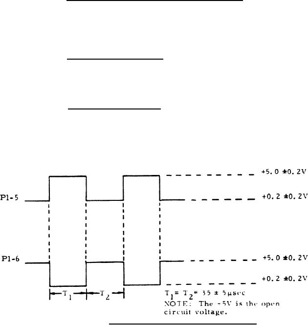
Figure 1. Converter Drive Signal Waveforms |
|
||
| ||||||||||
|
|  MIL-E-50739(MU
8 August 1973
3.3.1.3 Input voltage /charge current regulation. With the Power
source (item 2.1) of table I applied to P1-24 and adjusted to +18.0 0.5 Vdc
and then +30.0 0.5 Vdc, and the load (item 1.2) of table I connected as
specified, the current flowing through the specified load shall be 200 +80 mA
for each input condition.
3.3.1.4 Charger sense voltage. With the power source (item 2.1)
of table I applied to P1-24 and adjusted to +24.0 2.0 Vdc, and with the
load (item 1.2) of table I connected as specified, the voltage at P1-8 shall
be equal to the voltage at PI-4 within +1.5 Vdc.
3.3.1.5 Charge enable signal. With the power source (item 2.1)
of table I applied and adjusted to +24.0 2.0 Vdc, with the load (item 1.2)
of table I connected as specified, and with P1-10 disconnedted, from, P1-7,
the current flowing through the specified load shall be 0 +1O mA.
Figure 1. Converter Drive Signal Waveforms
5
|
|
Privacy Statement - Press Release - Copyright Information. - Contact Us |
