 |
|||
|
Page Title:
Fluid volume of the contaminant injection circuit |
|
||
| ||||||||||
|
|  MI L- F-24666 (SH)
required by 4.7.4.7 and may be adjusted by varying the level of the oil in the
reservoir.
A turbulent method in accordance with ANSI B93.19 shall be provided
for transferring fluid from the contaminant injection circuit to the element test
Samples for analysis shall
0.025 L/min
circuit to yield a flow rate of 0.5
be taken from the point of injection.
Sample analysis methods. Automatic particle counters shall be
4.7.4.5
used to determine the number and size distribution of particles in the fluid
samples taken from the element circuit. The particle counters shall be
calibrated in accordance with ANSI B93.18 for 3 and 5 micrometer sizes.
4.7.4.6 Test contaminant. The contaminant shall be standardized ACFTD
and shall be obtained from Naval Air Development Center (NADC), Warminster,
PA 18974. The amount of test dust (W) shall be at least 1.2 times the element
apparent capacity In milligrams (mg) to assure a sufficient amount of contaminant
for the test.
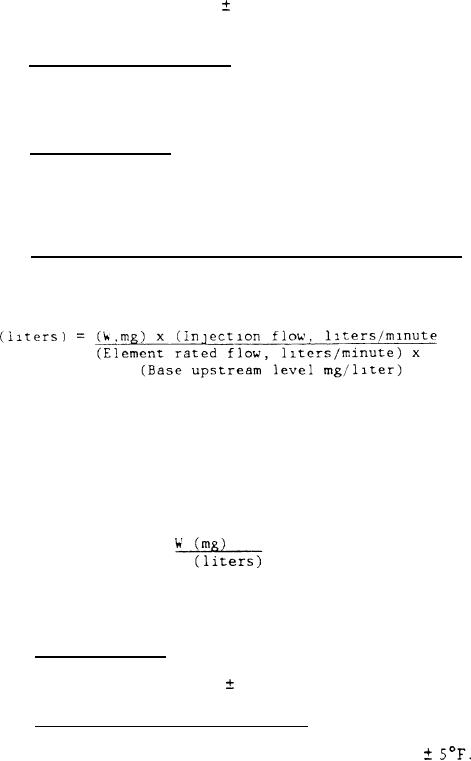
4.7.4.7 Fluid volume of the contaminant injection circuit. The fluid
volume of the contaminant injection circuit is related to the amount of
contaminant required to load the element and the element rated flow and shall
be determined as follows.
Where:
= Contaminant injection fluid volume, liters
W = Amount of test dust, mg (minimum) (see 4.7.4.6)
Injection flow = 0.5 liters/minute
10 mg/llter
Base upstream level:
Based on these values, the gravimetric level of the contaminant
injection circuit is:
Injection fluid volume may be increased as desired by increasing
Note:
the amount of test dust.
4.7.4.8 Test conditions.
(a) The test fluid (element test circuit and
(b) The
contaminant injection circuit) shall be oil conforming to MIL-H-5606.
test fluid temperature shall be 100
5F throughout the test.
4.7.4.9 Element test circuit validation. Adjust the volume of fluid in
Install a filter
the element test circuit to the required volume (see 4.7.4.3).
Contaminate
housing or conduit. Adjust test fluid temperature to 100
the circuit fluid to a calculated gravimetric level of 10 mg/L using ACFTD.
Circulate the fluid in the element test circuit at a rate equal to the element
flow rate plus or minus 5 percent. Fully open the valve at the upstream and
Circulate the fluid in the test system for 1 hour.
downstream-sample points.
With the automatic-particle counter sensors connected in-line, record cumulative
particle counts at 3 and 5 micrometers every 2 minutes, synchronizing the counting
periods of the two sensors. The validation test shall be accepted only if:
10
|
|
Privacy Statement - Press Release - Copyright Information. - Contact Us |
