 |
|||
|
Page Title:
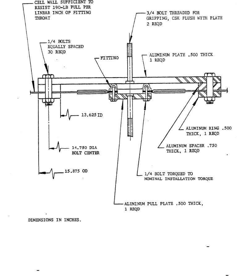
Figure 2. Fitting pullout test setup. |
|
||
| ||||||||||
|
|  MIL-F-5577B
FIGURE 2. Fitting pullout test setup.
ance shall be determined in accordance with
be removed from the oil, wiped dry,allowed to
ASTM Method D1149-55T. The test speci-
stand in fresh oil at room temperature for 4
mens shall consist of strips 0.075 + .005 by 1.0
hours, and the physical properties listed in
by 6.0 inches stretched 10 percent longitud-
table V shall be determined.
nally and held in this condition for the dura-
4.5.2.4 Types I and II fitting rubber stocks
tion of the test. The samples shall not crack
shall be subjected to a 7-day Geer oven cycle at
when exposed to an ozone concentration of 50
158 + 2 F. After cooling for at least 16 hours
parts per 100 million for 30 minutes at 100 + 2
in air, the physical proper-ties listed in table VI
F. A 7-power magnifying glass shall be used
shall be determined.
to examine the samples.
4.5.2.5 Ozone resistance. The ozone resist-
10
|
|
Privacy Statement - Press Release - Copyright Information. - Contact Us |
