 |
|||
|
|
|||
| ||||||||||
|
|  MIL-G-19027D(OS)
4.5.3.6.4 Connect a jumper between pins B-K of P201.
4.5.3.6.5 Measure the ac voltage across pins A-J of P201. The voltage
shall measure more than 160 volts. This is approximately zero setting.
NOTE
In order to obtain these measurements, it may
be necessary to change the synchro position
by running motor M202 electrically.
4.5.3.6.6 Remove jumper between pins B-K of P201, and measure ac volt-
age across pins J-L of P201. This voltage should be less than 0.3 volt.
4.5.3.6.7 Remove the voltages applied in 4.5.3.6.2 and 4.5.3.6.3.
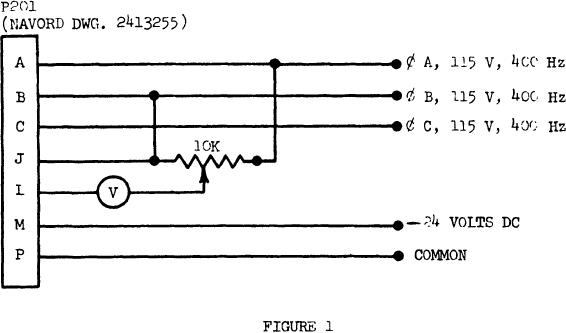
4.5.3.6.8 Connect the gyro as shown in Figure 1.
4.5.3.6.9 Adjust the 10k pot so that the ac voltmeter idicates 15
plus or minus 2 volts.
4.5.3.6.10 Uncage the gyro (remove power source from pins M-P of P201),
and manually turn the gyro in a counterclockwise direction (5 to 10 degrees)
as viewed from above. This shall increase the voltmeter reading.
4.5.3.6.11 This completes the test for electrical zeroing. Disconnect
all power sources and remove all connections shown in Figure 1. Allow
the gyro to cool to ambient before proceeding on the next tests.
14
|
|
Privacy Statement - Press Release - Copyright Information. - Contact Us |