 |
|||
|
|
|||
| ||||||||||
|
|  MIL-I-19028E(OS)
3.3.2.4.2 Grounds. No circuit within the inverter shall be con-
nected to the inverter frame.
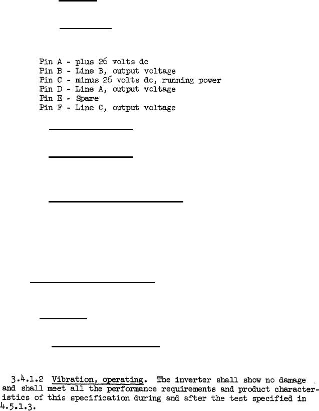
3.3.2.4.3 Receptacle. The inverter control box shall mount a
receptacle, MS-3102-A-20-22P, as shown in Dwg 1263725. Receptacle
pins shall be utilized as follows:
3.3.2.5 Brush replacement. Brushes shall be accessible for re-
placement when the brush opening covers are removed.
3.3.2.6 Schematic diagram. Attached
to the inside of the control
box shall be a complete circuit diagram
describing all the electrical
component values of the equipment. The
diagram shall be legible, pro-
tected against humidity, and not easily
removed.
3.3.2.7 Setting-means identification. The location of the output
voltage and frequency setting device shall be identified on the inverter.
Marking shall be legible, protected against humidity, and not easily
removed.
3.3.2.8 The conducted and radiated interference when tested over the
AN/ARM-6 Range (14 to 250 kHz) and as prescribed in 4.4.8 shall not
exceed the limits given in Figures 1 and 2.
3.4 Environmental requirements. The inverter shall meet the other
applicable requirements of this specification during or after the
tests defined or specified in 4.5.
3.4.1 Vibration.
The inverter shall meet the following vibration
requirements:
3.4.1.1 Vibration, nonoperating. The inverter shall show no damage
and shall meet all the performance requirements and product character-
istics of this specification after being tested as in 4.5.1.2.
10
|
|
Privacy Statement - Press Release - Copyright Information. - Contact Us |
