 |
|||
|
Page Title:
Table VI - Dielectric test voltages. |
|
||
| ||||||||||
|
|  MIL-M-17059A(SHIPS)
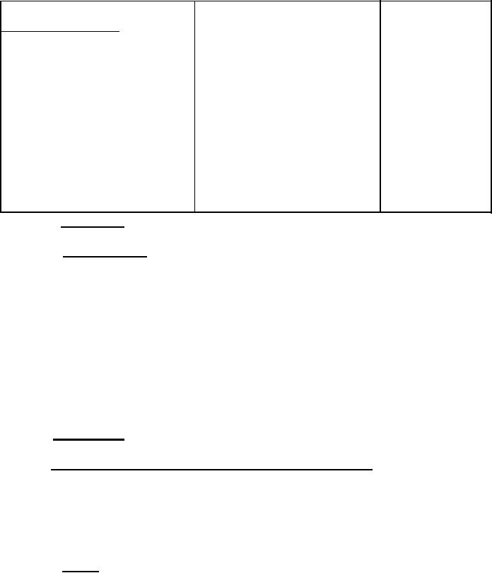
Table VI - Dielectric test voltages.
Minimum
Test voltage
Part
duration
Secondary windings of wound
rotors:
1,000 plus twice normal induced
1 minute
Nonreversing
voltage on open circuit.
1,000 plus four times normal
1 minute
Reversing, while running at
approximately normal speed
induced voltage on open circuit.
by reversing the primary con-
nections
Motors rated 1/2 H. p. and
1,000 plus twice rated voltage
1 minute
larger
Motors rated less than 1/2 H. P.
900 volts
1 minute
(a) Motors rated 250
volts or less
1,000 plus twice normal induced
(b) Motors rated over
1 minute
250 volts
voltage on open circuit
3.1.14.1 Alternate test. - An alternating-current test voltage of 1.2 times the one-minute test voltage
specified above may be applied for 1 second as an alternative to the l-minute test.
3.1.15 Mechanical balance. - Motors shall be balanced at any load and speed in the operating range.
Windings not in mechanical symmetry shall have dummy coils. In general, the proper mechanical balance
shall be effected by the use of balance weights securely attached, (if bolts are used, corrosion-resistant
bolts and locknuts shall be used), removal of material, securely welded steel weights, or by metal carried
in a receiver in such a manner as to preclude its breaking loose. Balancing by the use of solder on the
banding wire is permissible subject to the following limitations:
(a)
Peripheral speed not to exceed 6,500 feet per minute at rated load.
(b)
All armatures to be balanced before the windings are inserted.
(c)
Only tinned banding wire is to be used.
(d)
The solder not to cover an arc of more than 25 percent of the circumference of the armature
measured on the banding wire unless satisfactory to the bureau or agency concerned. Where
the manufacturer prebalances the armature and takes care in placing the windings in the
slots to reduce unbalance due to axial misalignment of the coils, this value may be increased
to 33 percent if satisfactory to the bureau or agency concerned.
(See 3.5.1.5 for service A and 3.5.1.17.5 for submarine requirements.)
3.1.16 Frame and feet. - The frame shall be of rigid construction. The feet shall be machined and
the holes for holding-down bolts may be either drilled or slotted.
3.1.17 End shields (explosionproof and explosionproof, fan-cooled excluded). - An accurate shoulder
joint shall be provided between the frame and end shields. When so specified (see 6. 1), the design of the
end shields shall provide for the rotation of the shields through 90 degrees or 180 degrees in either direction
to allow for bulkhead or underside suspension of the motor. Resilient-gaskets shall not be placed between
any bearing support member and the frame in such a manner as to affect the alignment of the bearing. In
the case of spraytight, watertight and submersible motors, the contact surfaces between the enclosing covers
and the motor frame or end shields shall be free from fins, burrs, or other imperfections detrimental to
watertightness, and shall be provided with "O" rings or gaskets suitably secured and treated with graphite
on the contact surface to prevent sticking. All sheet packing shall be securely attached to the covers.
3.1.17.1 General. - The end shields shall be secured by not less than two machine screws or through
bolts of suitable size and strength. These machine screws or through bolts may be furnished with either
screw-driver slots or hexagon-head screws.
|
|
Privacy Statement - Press Release - Copyright Information. - Contact Us |
