 |
|||
|
|
|||
| ||||||||||
|
|  MIL-M-17413A(NAVY)
3.2.9 Overspeed. - Except for submarine motors (see 3.7. 4), motors except varying speed motors
shall withstand without injury, continuous speeds of 125 percent of maximum no-load speed. Varying
speed motors that have no definite no-load speed shall withstand a continuous speed of not less than
200 percent of the rated full-load speed of the driven auxillary except that where the maximum speed of
the auxiliary under normal operating conditions exceeds 200 Percent of rated full-load speed, the motor
shall withstand this maximum speed.
3.2.10 Insulation resistance - The insulation resistance, when corrected to 25C. , shall be not
less than the following:
Armature circuit (class A insulated) -12 megohms.
Armature circuit (class B and H insulated) -25 megohms.
Field circuit (class A insulated) -25 megohms.
Field circuit (class B and H insulated) -50 megohms.
3.2.11 Dielectric strength. - Motors shall be capable of withstanding a dielectric test voltage equal
to twice the rated value of the terminal voltage plus 1,000 volts at a frequency of not less than 60 cycles
per second. The voltage wave shall approximiate a sine wave. The testing voltage shall be applied con-
tinuously for a period of not less than 1 minute. As an alternate, motors for which the test voltage is
2,500 volts or less may be tested for not less than 1 second with a test voltage 20 percent higher than the
l-minute test voltage.
3.2.12 Dynamic balance. - Motors shall be balanced at any load and speed in the operating range.
Windings not in mechanical symmetry shall have dummy coils. In general, the proper mechanical balance
shall be effected by the use of balance steel weights attached by noncorrodible bolts securely locked,
drilling out of material, securely welded steel weights, or by babbitt carried in a receiver in such a
manner as to preclude its breaking loose. Balancing by the use of solder on the banding wire is permis-
sible subject to the following limitations:
(a)
Diameter of the rotor not to exceed 16 inches.
(b)
Peripheral speed not to exceed 6,500 feet per minute at rated load.
(c)
All armature cores to be balanced before the windings are inserted.
(d)
Only tinned banding wire is to be used.
(e)
The solder not to cover an arc of more than 25 percent of the circumference of the
armature measured on the banding wire unless satisfactory to the bureau or agency
concerned. Where the manufacturer pre-balances the armature and takes care in
placing the windings in the slots to reduce unbalance due to axial misalignment of
the coils, this value may be increased to 33-1/2 percent if satisfactory to the bureau
or agency concerned.
(f) Thickness of solder over banding wire not to exceed 3/32 inch, and in no case to
extend past the center of the air gap.
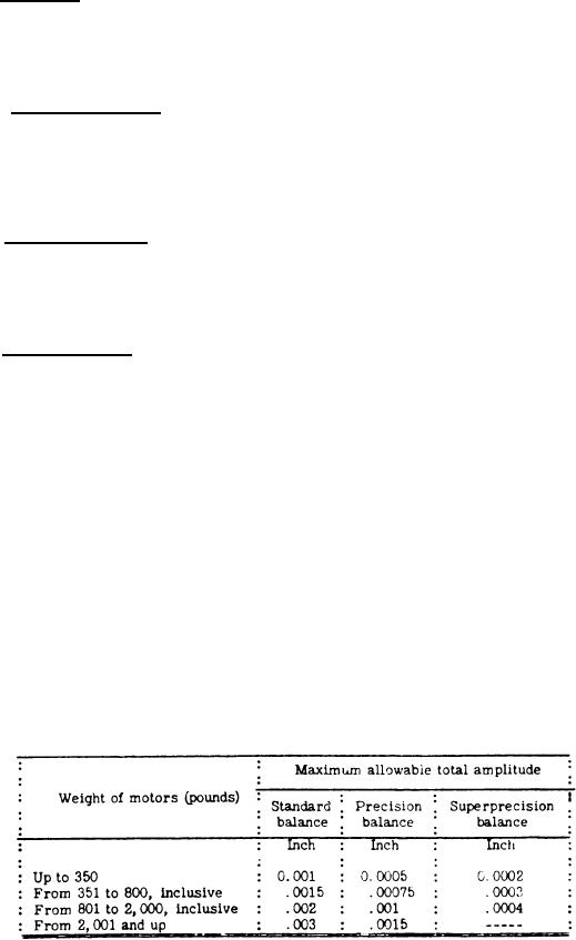
3.2.12.1 The degree of balance shall be "standard" in accordance with table I unless otherwise speci-
fied (see 6. 2). For submarine motors see 3.7.12. When tested as specified in 4.2.4.6.1, the maximum
allowable amplitude in inches shall be in accordance with table I.
Table I - Maximum allowable amplitude.
6
|
|
Privacy Statement - Press Release - Copyright Information. - Contact Us |
