 |
|||
|
Page Title:
Figure 4. Case outline Y (device types 04, 05, and 06). |
|
||
| ||||||||||
|
| 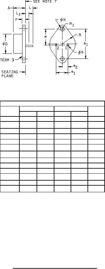 MIL-M-38510/117C
Dimensions
Symbol
Inches
Millimeters
Notes
Min
Max
Min
Max
A
.250
.450
6.35
11.43
1.177
1.197
29.90
30.40
A1
φb
.038
.043
.97
1.09
3,7
φD
---
.875
---
22.22
e
.655
.675
16.64
17.14
.420
.440
10.67
11.18
e1
.205
.225
5.21
5.72
e2
F
.060
.135
1.52
3.43
φH
.151
.161
3.84
4.09
5,6
L
.312
.500
7.92
12.70
4
---
.050
---
1.27
3,5
L1
R
.495
.525
12.57
13.34
.131
.188
3.33
4.78
R1
NOTES:
1. Dimensions are in inches.
2. Metric equivalents are given for general information only and are based upon 1.00 inch = 25.4 mm.
3. (Two leads) φb applies between L1 and .500 (12.70 mm) from the seating plane.
Diameter is uncontrolled in L1 and beyond .500 (12.70 mm) from the seating plane.
4.
Two leads.
5.
Two holes.
6.
Two holes located at true position within diameter .010 (.25 mm).
7.
Leads having a maximum diameter .043 (1.09 mm) measured in gaging plane .054 (1.37 mm) + .001 (.03 mm) -
.000 (.00 mm) below the seating plane shall be located at true position within diameter .014 (.36 mm).
8.
The mounting surface of the header shall be flat to convex within .003 (.08 mm) inside a .930 (23.62 mm)
diameter circle on the center of the header and flat to convex within .006 (.15 mm) overall.
FIGURE 4. Case outline Y (device types 04, 05, and 06).
24
|
|
Privacy Statement - Press Release - Copyright Information. - Contact Us |
