 |
|||
|
Page Title:
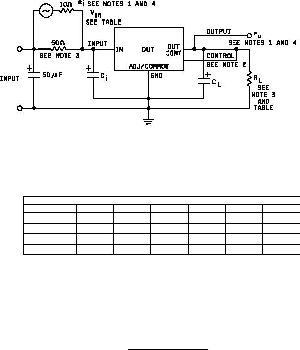
Figure 11. Ripple rejection test circuit. |
|
||
| ||||||||||
|
|  MIL-M-38510/117C
Device table
Device types
01
02
03
04
05
06
10 V
10 V
6.25 V
6.25 V
6.25 V
6.25 V
VIN
40.2 Ω
14.3 Ω
10 Ω
2.5 Ω
2.5 Ω
2.5 Ω
RL
0.33 F
0.33 F
1.0 F
1.0 F
1.0 F
1.0 F
Ci
0.1 F
0.1 F
1.0 F
1.0 F
1.0 F
1.0 F
CL
NOTES:
1. ei = 1 Vrms at f = 2400 Hz (measured at the input terminals of the DUT).
Ripple rejection = 20 log (eirms / eorms).
2.
The control pin connection is required for device types 01 and 02 only.
The input 50 Ω resistor and RL shall be type RER 70 or equivalent.
3.
4.
The meter for ei and eo shall have a minimum bandwidth from 10 Hz to 10 kHz for devices 01 05 and
300 Hz to 10 kHz for device type 06 shall measure true rms voltages.
FIGURE 11. Ripple rejection test circuit.
35
|
|
Privacy Statement - Press Release - Copyright Information. - Contact Us |
