 |
|||
|
Page Title:
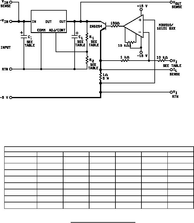
Figure 14. Load transient response test circuit. |
|
||
| ||||||||||
|
|  MIL-M-38510/117C
Device table
Device type
01
02
03
04
05
06
249 Ω
249 Ω
249 Ω
249 Ω
0
0
R1
1.0 kΩ
1.0 kΩ
0
0
0
0
R2
-50 mA
-100 mA
-50 mA
-100 mA
-100 mA
-100 mA
IL
-200 mA
-400 mA
-200 mA
-400 mA
-400 mA
-400 mA
ĆIL
-0.45 V
-0.95 V
-0.45 V
-0.95 V
-0.95 V
-0.95 V
VI
-2.0 V
-4.0 V
-2.0 V
-4.0 V
-4.0 V
-4.0 V
ĆVI
0.33 F
0.33 F
1.0 F
1.0 F
1.0 F
1.0 F
Ci
0.1 F
0.1 F
1.0 F
1.0 F
1.0 F
1.0 F
CL
FIGURE 14. Load transient response test circuit.
38
|
|
Privacy Statement - Press Release - Copyright Information. - Contact Us |
