 |
|||
|
Page Title:
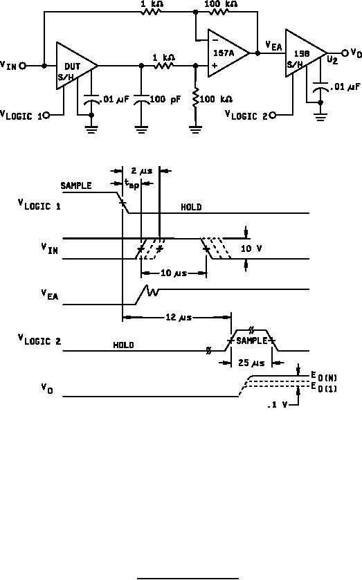
Figure 12. Aperture time test circuit. |
|
||
| ||||||||||
|
|  MIL-M-38510/125B
NOTES:
1. Aperture time is equal to the time delay from the VLOGIC 1 device under test (D.U.T.) `hold' command
step to the 10 V input transition which yields a 0.1 volt output error from its 2 s delayed value E0(1).
2. A flow chart for the automatic determination of aperture time is shown in figure 13. All four combinations
of 10 V input and 5 V logic signals shall be checked.
3. The adapter S/H U2 holds the `data' voltage for the measurement system.
FIGURE 12. Aperture time test circuit.
22
|
|
Privacy Statement - Press Release - Copyright Information. - Contact Us |
