 |
|||
|
Page Title:
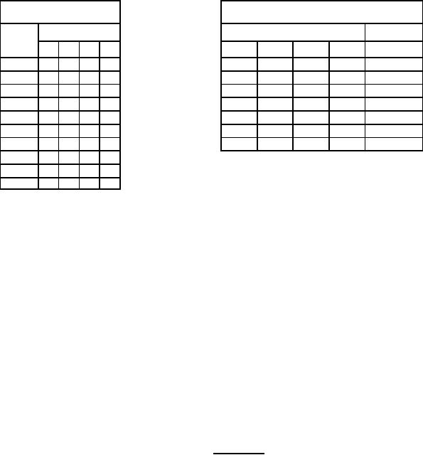
Figure 3. Truth tables device type 07 |
|
||
| ||||||||||
|
|  MIL-M-38510/13G
DEVICE TYPE 07
BCD count sequence
(see note 1)
Reset count (see note 2)
Output
Reset inputs
Output
Count
D
C
B
A
R0(1)
R0(2)
R9(1)
R9(2)
D C B A
0
L
L
L
L
H
H
L
X
L L L L
1
L
L
L
H
H
H
X
L
L L L L
2
L
L
H
L
X
X
H
H
H L L H
3
L
L
H
H
X
L
X
L
COUNT
4
L
H
L
L
L
X
L
X
COUNT
5
L
H
L
H
L
X
X
L
COUNT
6
L
H
H
L
X
L
L
X
COUNT
7
L
H
H
H
NC No internal connection.
8
H
L
L
L
9
H
L
L
H
NOTES:
1. Output A connected to input BD for BCD count.
2. X indicates that either a logical H or a logical L may be present.
3. When used as a binary coded decimal decade counter, the BD input must be externally
connected to the A output. The A input receives the incoming count, and a count sequence is
obtained in accordance with the BCD count sequence truth table shown above. In addition to
a conventional zero reset, inputs are provided to reset a BCD count for nine's complement
decimal applications.
4. If a symmetrical divide-by-ten count is desired for frequency synthesizers or other applications
requiring division of a binary count by a power of ten, the D output must be externally connected
to the A input. The input count is then applied at the BD input and a divide-by-ten square wave is
obtained at output A.
5. For operation as a divide-by-two counter and a divide-by-five counter, no external interconnections
are required. Flip-flop A is used as a binary element for the divide-by-two function. The BD input
is used to obtain binary divide-by-five operation at the B, C, and D outputs. In this mode, the two
counters operate independently; however, all four flip-flops are reset simultaneously.
FIGURE 3. Truth tables - Continued.
25
|
|
Privacy Statement - Press Release - Copyright Information. - Contact Us |