 |
|||
|
Page Title:
Figure 8. Timing diagrams (system controlled operation)-cont. |
|
||
| ||||||||||
|
|  MIL-M-38510/140A
Test setup timing specifications
CONVERT MODE
Symbol
Parameter
Min
Unit
CE pulse width
300
ns
tHEC
300
ns
tSSC
CS to CE setup
200
ns
tHSC
CS low during CE high
250
ns
tSRC
R/ C to CE setup
200
ns
tHRC
R/ C low during CE high
0
ns
tSAC
A0 to CE setup
300
ns
tHAC
A0 valid during CE high
READ MODE
Symbol
Parameter
Min
Unit
150
ns
tSSR
CS to CE setup
0
ns
tSRR
R/ C to CE setup
150
ns
tSAR
A0 to CE setup
50
ns
tHSR
CS valid after CE low
0
ns
tHRR
R/ C high after CE low
50
ns
tHAR
A0 valid after CE low
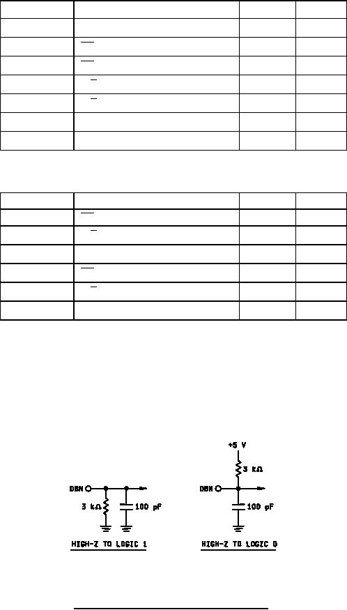
NOTES:
1. Test parameter tDD is measured with the following load circuit and the access time is defined as the
time required for an output to reach 0.4 V and 2.4 V for VOL and VOH, respectively.
2. Test parameters tHL and tHD are measured with the following load circuit and the float delay time
are defined as the time required for an output to reach 0.8 V to 2.0 V from a logic "0" and from a logic "1".,
respectively.
FIGURE 8. Timing diagrams (system controlled operation) Continued.
24
|
|
Privacy Statement - Press Release - Copyright Information. - Contact Us |
