 |
|||
|
Page Title:
Figure 9. Timing diagrams (stand alone operation)-cont. |
|
||
| ||||||||||
|
|  MIL-M-38510/140A
Test setup timing specifications
STAND ALONE MODE
Symbol
Parameter
Min
Unit
350
ns
tHRL
Low R/ C pulse width
250
ns
tHRH
High R/ C pulse width
NOTE: For stand-alone operation, CE is tied to logic "1", 12/ 8 is wired to +5 V, and CS and A0
are tied to logic "0".
Test parameter tRR is measured with the following load circuit and the access time is defined as the
time required for an output to reach 0.4 V and 2.4 V for VOL and VOH, respectively.
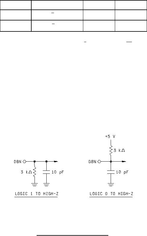
Test parameter tHDR is measured with the following load circuit and the float delay time is defined as the
time required for an output to reach 0.8 V and 2.0 V from a logic "0" and from "1", respectively.
FIGURE 9. Timing diagrams (stand alone operation) Continued.
26
|
|
Privacy Statement - Press Release - Copyright Information. - Contact Us |
