 |
|||
|
Page Title:
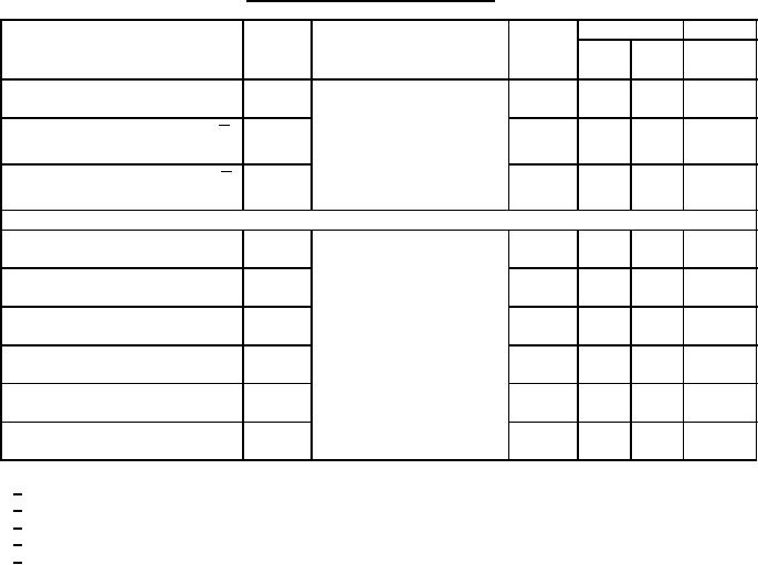
Table 1. Electrical performance characteristics-cont. |
|
||
| ||||||||||
|
|  MIL-M-38510/15B
TABLE I. Electrical performance characteristics Continued
Test
Limits
Unit
Device
Symbol
Conditions
-55C ≤ TC ≤ +125C
types
Min
Max
unless otherwise specified
CL = 50 pF 10%;
To high level, from clock input to Q tPLH3
01, 02
2
44
ns
output
RL = 390 ohms 5%
01
2
25
ns
To low level, from clock input to Q tPHL4
output
01
2
44
ns
To high level from clock input to Q tPLH4
output
Propagation delay time for types 03 and 04
CL = 50 pF 10%;
To high level, from enable to
tPLH1
03, 04
3
60
ns
output
RL = 390 ohms 5%
To low level, from enable to
tPHL1
03, 04
3
40
ns
output
To high level, from data to
tPLH2
03, 04
3
49
ns
output
To low level, from data to
tPHL2
03, 04
3
37
ns
output
To low level, from master reset
tPHL3
03, 04
3
37
ns
to output
To high level, from set to
tPLH4
04
9
47
ns
output
1/
All unspecified inputs at 5.5 V.
2/
All unspecified inputs grounded.
3/
Not more than one output should be shorted at a time.
4/
Circuit B limits for IIL1 shall be -1.6 mA, maximum.
5/
Circuit B and C limits for IOS shall be -20 mA minimum to -57 mA maximum.
5
|
|
Privacy Statement - Press Release - Copyright Information. - Contact Us |
