 |
|||
|
Page Title:
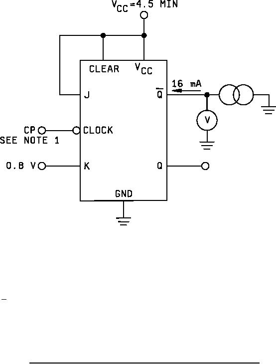
Figure 15. Input clamp voltage test circuit for device types 01, 02, 03, and 04 (circuit B). |
|
||
| ||||||||||
|
|  MIL-M-38510/2G
NOTES:
1. Apply normal clock pulse, then sink -12 mA on the clock input.
2. The output Q is measured after -12 mA is applied to the clock to insure it is still in the low state.
FIGURE 15. Input clamp voltage test circuit for device types 01, 02, 03, and 04 (circuit B).
35
|
|
Privacy Statement - Press Release - Copyright Information. - Contact Us |
