 |
|||
|
Page Title:
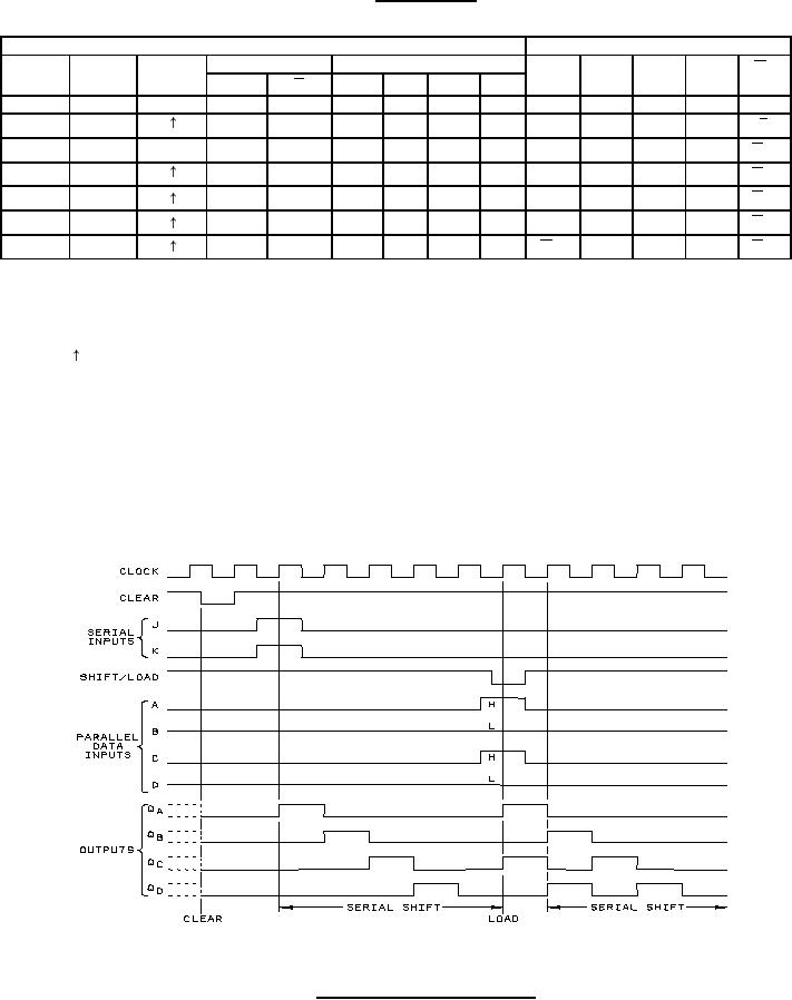
Figure 2. Truth tables and timing diagrams Device type 02 |
|
||
| ||||||||||
|
|  MIL-M-38510/306E
Device type 02
INPUTS
OUTPUTS
SHIFT/
SERIAL
PARALLEL
QD
CLEAR
CLOCK
QA
QB
QC
QD
LOAD
J
A
B
C
D
K
L
X
X
X
X
X
X
X
X
L
L
L
L
H
H
L
X
X
a
b
c
d
a
b
c
d
d
H
H
L
X
X
X
X
X
X
QA0
QB0
QC0
QD0
Q D0
H
H
L
H
X
X
X
X
QA0
QA0
QBn
QCn
Q Cn
H
H
L
L
X
X
X
X
L
QAn
QBn
QCn
Q Cn
H
H
H
H
X
X
X
X
H
QAn
QBn
QCn
Q Cn
H
H
H
L
X
X
X
X
QBn
QCn
QAn
Q An
Q Cn
H = high level (steady state)
L = low level (steady state)
X = irrelevant (any input, including transitions)
= transition from low to high level
a, b, c, d = the level of steady state input at inputs A, B, C, or D, respectively.
QA0, QB0, QC0, QD0 = level of QA, QB, QC, or QD, respectively, before the
indicated steady state input conditions were established.
QAn, QBn, QCn, = the level of QA, QB, or QC, respectively, before the most
recent transition of the clock.
Typical clear, shift, and load sequences.
FIGURE 2. Truth tables and timing diagrams - Continued.
16
|
|
Privacy Statement - Press Release - Copyright Information. - Contact Us |
