 |
|||
|
Page Title:
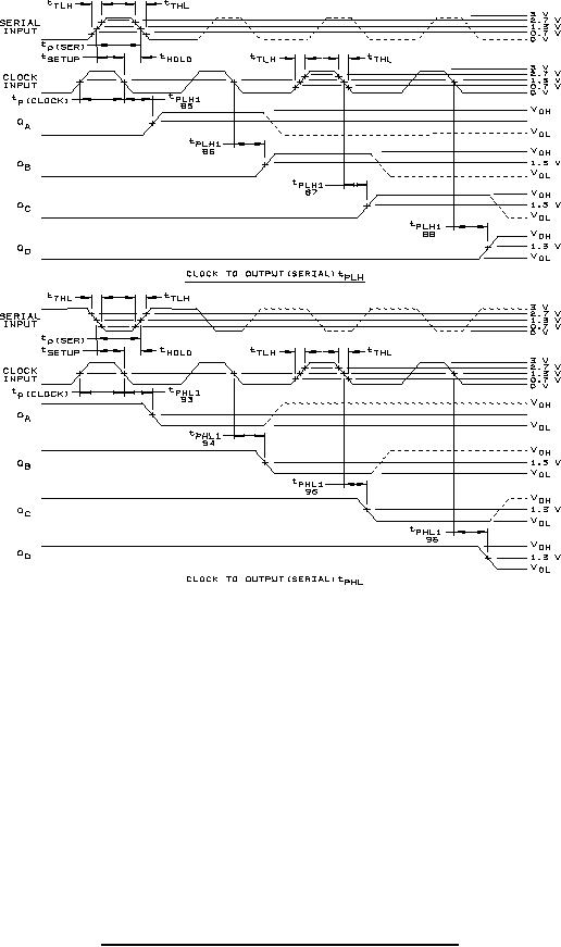
Figure 9. Switching test circuit and waveforms for device type 06-cont. |
|
||
| ||||||||||
|
|  MIL-M-38510/306E
NOTES:
1. Clock pulse characteristics: PRR ≤ 1.0 MHz, tTLH ≤ 15 ns, tTHL ≤ 6 ns, tp (clock) ≥ 25 ns.
2. Data or serial pulse characteristics: tTLH ≤ 15 ns, tTHL ≤ 6 ns, tp (serial) or tp (data)
= 40 ns, tSETUP = 20 ns, tHOLD = 20 ns.
3. Output control characteristics: tTLH ≤ 15 ns, tTHL ≤ 6 ns, tp (control) ≥ 100 ns,
except when optional load is used, CL = 50 pF 10% for all tests.
4. CL = 50 pF 10% for propagation delay, tZL, tZH, and CL = 15pF minimum for tHZ, tLZ
except when optional load is used, CL = pF 10% for all tests.
CL includes scope probe, wiring, and stray capacitance without package in test fixture.
All diodes are 1N3064, 1N916, or equivalent.
6. RL = 680 Ω 5%.
7. Prior to initiating tests, the output shall be placed in the proper state.
FIGURE 9. Switching test circuit and waveforms for device type 06 - Continued.
48
|
|
Privacy Statement - Press Release - Copyright Information. - Contact Us |
